background image

6

PROCEDURE 1

PREPARING WHEELCHAIR

P
R

E

P

A

R

I

N

G

W

H

E
E

L

C

H

A

I

R

This Procedure includes the following:

Installing/Removing Cane Clamps

Installing Inserts

INSTALLING/REMOVING CANE
CLAMPS (FIGURE 1)

NOTE: Refer to the INSTALLATION AND STABILITY
WARNINGS
 in the SAFETY SUMMARY of this manual.

Installing Cane Clamps

WARNING

DO NOT modify cane clamps to fit 3/4-
inch tubing. Clamps provided are for 1-
inch or 7/8-inch tubing ONLY.

NOTE: The final positions of the upper (swivel) and lower
(fixed) cane clamps will be determined by the adjustments
made to the Infinity Back to fit the wheelchair and user.

1. Remove existing back upholstery. Refer to wheelchair

owner's manual.

2. Loosen, but do not remove the mounting screw on

the cane clamp with allen wrench provided.

3. Perform one (1) of the following:

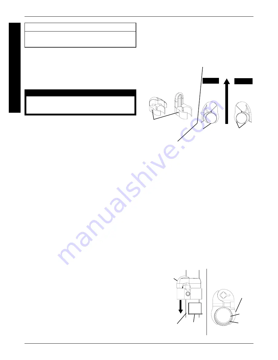
UPPER (SWIVEL) CLAMPS - Visually inspect the
clamps to determine whether they are for the RIGHT
or LEFT back cane as shown in FIGURE 1.

NOTE: The upper (swivel) cane clamps are marked
with R for RIGHT and L for LEFT.

NOTE: RIGHT and LEFT are determined by sitting
in the wheelchair.

LOWER (FIXED) CLAMPS - Proceed to STEP 4.

4. Hold the Infinity Back up to the back canes of the wheel-

chair at the desired mounting height.

5. Visually inspect the location of the mounting pins on

the Infinity Back to determine the proper positions for
each cane clamp.

6. Position the clamp on the back cane at the desired

height so that the open end of the clamp is facing the
REAR of the back cane as shown in FIGURE 1.

7. Torque mounting screw to 45-50 in./lbs.

8. Perform one (1) of the following:

A. If cane clamp holds desired mounting position,

proceed to STEP 9.

B. If cane clamp DOES NOT hold desired mount-

ing position, clamp is too large - refer to INSTALL-
ING  INSERTS 
in this procedure of the manual.

9. Repeat STEPS 2 - 8 for remaining cane clamp(s).

FIGURE 2 - INSTALLING INSERTS

Clamp

Half

Insert

FRONT OF

WHEELCHAIR

Back

Cane

Removing Cane Clamps

1. Remove the Infinity Back from the wheelchair. Refer

to REMOVING THE INFINITY BACK in PROCE-
DURE 3
 of this manual.

2. Loosen, but do not remove the mounting screw on

the cane clamp.

3. Remove cane clamp from back cane.

Slide Clamp

OVER Insert

Insert

Clamp

SIDE VIEW

Back Cane

INSTALLING INSERTS (FIGURE 2)

NOTE: Refer to the INSTALLATION AND STABILITY
WARNINGS 
in the SAFETY SUMMARY of this manual.

NOTE: This procedure should be performed only if cane
clamps are too large for back cane tubing.

1. Loosen the mounting screw in the cane clamp.

NOTE: Mounting screw should be loosened enough to
create space for the insert to fit between the back cane
and the cane clamp.

2. Position one (1) insert onto the back cane near the cane

clamps with the opening facing the front of the wheelchair.

3. Slide the cane clamp over the insert until the clamp

halves surround the insert as shown in FIGURE 2.

4. Torque mounting screw to 45-50 in./lbs.

NOTE: If clamps are still to large for back canes, DO
NOT use. Contact Invacare at the number on the back
page of this manual.

FIGURE 1 - INSTALLING/REMOVING

CANE CLAMPS

RIGHT

Upper

Cane

Clamp

LEFT

Upper

Cane

Clamp

Upper

(Swivel)

Cane

Clamp

Lower

(Fixed) Cane

Clamp

Mounting

Screw

WHEELCHAIR

FRONT

Back Cane

TOP VIEW

Open End

of Clamp

TOP VIEW

FRONT OF

WHEELCHAIR

Summary of Contents for Infinity Back Support

Page 1: ...INFINITY BACK SUPPORTS Assembly Installation and OperationInstructions ...

Page 2: ...onal injury or property damage SPECIAL NOTES SPECIAL NOTES 2 SAFETY SUMMARY 3 IMPORTANT INFORMATION 5 INSTALLATION ADJUSTMENT OVERVIEW 5 PROCEDURE 1 PREPARING WHEELCHAIR 6 INSTALLING REMOVINGCANECLAMPS 6 INSTALLINGINSERTS 6 PROCEDURE 2 PREPARING THE INFINITY BACK FOR INSTALLATION 7 INSTALLING REMOVINGTHE LATERAL SUPPORTS 7 INSTALLING REMOVINGCUSHIONS 7 ADJUSTING THE MOUNTING HARDWARE 9 TABLE OF CO...

Page 3: ...ll attaching hard ware is tightened securely otherwise injury or damage may occur STABILITY WARNINGS The seat height seat depth back height tilt angle back angle pivot point of seat frame seating system caster position size and position of the rear wheels wheel locks anti tippers locking collar as well as the user condition directly relate to the stability of the wheelchair Any change to one 1 or ...

Page 4: ...cline MUST be limited to prevent the wheelchair from tipping onto the anti tippers The necessary back angle MUST be selected BEFORE repositioning rear wheels forward AS REGARDS RESTRAINTS SEAT POSITIONING STRAPS IT IS THE OBLIGATION OF THE DME DEALER THERAPISTS AND OTHER HEALTH CARE PROFESSIONALS TO DETERMINE IF A SEAT POSI TIONING STRAP IS REQUIRED TO ENSURE THE SAFE OPERATION OF THIS EQUIPMENT B...

Page 5: ...he wheelchair Refer to INSTALLING REMOVING CANE CLAMPS in PROCEDURE 1 of this manual STEP 5 Install the Infinity Back Refer to INSTALLING THE INFINITY BACK in PROCE DURE 3 of this manual STEP 7 Adjust the depth of the Infinity Back Refer to ADJUSTING THE DEPTH HARDWARE in PROCEDURE 4 of this manual STEP 4 Adjust the mounting hardware Refer to ADJUSTING THE MOUNTING HARDWARE in PROCEDURE 2 of this ...

Page 6: ...ing screw to 45 50 in lbs 8 Perform one 1 of the following A If cane clamp holds desired mounting position proceed to STEP 9 B If cane clamp DOES NOT hold desired mount ingposition clampistoolarge refertoINSTALL ING INSERTS in this procedure of the manual 9 Repeat STEPS 2 8 for remaining cane clamp s FIGURE 2 INSTALLING INSERTS Clamp Half Insert FRONT OF WHEELCHAIR Back Cane Removing Cane Clamps 1...

Page 7: ...tyBackhasbeeninstalledonthe wheelchairandtheuserhasbeenevaluated 7 Repeat STEPS 2 6 for the other mounting screw for thislateralsupport 8 RepeatSTEPS2 7 fortheremaininglateralsupports 9 Install the back cushion on the back panel Refer to INSTALLING REMOVING CUSHIONS in this pro cedureofthemanual Removing 1 Removethebackcushionfromthebackpanel Refer toINSTALLING REMOVINGCUSHIONSinthispro cedureofth...

Page 8: ...he top flap up and pull the bottom flap down on the back cushion cover 2 Position the cushion against the back panel s with the flaps on the outside of the Infinity Back NOTE Ensurethelateralsupportsarepositionedbetween the back cushion foam and the elastic strips on either side of the back cushion cover as shown in FIGURE 2 3 If desired install the adjustable positioning pad UniBack only onto the...

Page 9: ...allationheight 2 VisuallyinspecteachsideoftheInfinityBacktoseeifthe widthhardwareissetattheappropriateheighttomatch theclampinstallationand orthebackcaneconfiguration 3 Perform one 1 of the following CORRECT HEIGHT Adjust the width of the width hardware Refer to ADJUSTING THE MOUNTING HARDWARE WIDTH in this pro cedureofthemanual INCORRECT HEIGHT Adjust the height of the width hardware Refer to ADJ...

Page 10: ...eelchairtodeterminewhich adjustments need to be made to properly fit the Infinity Back Refertothewheelchairowner smanual 9 Removetheuserfromthewheelchair Refertothewheel chair owner s manual 10 Perform the following procedures to adjust the Infin ity Back to fit the wheelchair and the user if neces sary Refer to PROCEDURE 4 ADJUSTING THE INFINITY BACK in this manual A ADJUSTING THE HINGE ANGLE DUA...

Page 11: ...VING THE INFINITY BACK in PROCEDURE 3 of this manual NOTE After performing each procedure reinstall the back place the user in the wheelchair and inspect to ensure the correctadjustmentshavebeenmadeforusercomfort Ifnec essary repeattheprocedureuntiltheuseriscomfortable ADJUSTING CANE CLAMP HEIGHT FIGURE 1 NOTE Refer to the INSTALLATION AND STABILITY WARNINGS in the SAFETY SUMMARY of this manual 1 ...

Page 12: ...the desired depth 6 Torquemountingscrewto45 50in lbs tosecuredepth brackettowidthbracket 7 Perform one 1 of the following DUALFLEX Adjustthehingeand orangleoftheback ifpresent RefertoADJUSTINGTHEHINGE ANGLE inthisprocedureofthemanual UNIBACK ProceedtoADJUSTINGTHELATERAL SUPPORTS in this procedure of the manual ADJUSTING THE LATERAL SUPPORTS FIGURE 5 NOTE Refer to the INSTALLATION AND STABILITY WAR...

Page 13: ...hecurvedwasheronthemountingscrewso thatthebentportionisTOWARDtheheadofthemount ing screw as shown in DETAIL A of FIGURE 5 5 RepeatSTEPS2 4fortheremainingmountingscrew and washers 6 Positionthelateralsupportin theupper middleorlower position aligning the mounting holes of the support with the adjustment slot in the Infinity Back as shown in DE TAIL B ofFIGURE5 NOTE The grooves next to the mounting ...

Page 14: ...ANCE M A I N T E N A N C E This Procedure includes the following Installing Removing Cushion Foam Inspection Cleaning Top Flap Top of Cushion Foam Elastic Strip Installing Removing Lateral Support Cushion Foam FIGURE 2 INSTALLING 1 Remove the lateral support cushion from the lateral support RefertoINSTALLING REMOVINGCUSH IONS in PROCEDURE 2 of this manual 2 Position the cushion cover on a flat sur...

Page 15: ...e adjustable positioning pad and pull to re lease the fastening strips 4 InstallthebackcushionontotheInfinityBack Referto INSTALLING REMOVING CUSHIONS inPROCE DURE 2 of this manual Bottom Flap Adjustable Positioning Pad Fastening Strips Top Flap Back Cushion Back Cushion Foam FIGURE 3 INSTALLING REMVOING ADJUSTABLE POSITIONING PAD UNIBACK ONLY INSPECTION WARNING DO NOT continue to use this product...

Page 16: ...lease write directly to Invacare at the address at the bottom of this page Provide dealer s name address date of purchase indicate nature of the defect and if the product is serialized indicate the serial number Do not return products to our factory without our prior con sent LIMITATIONS AND EXCLUSIONS THE FOREGOING WARRANTY SHALL NOT APPLY TO SERIAL NUMBERED PRODUCTS IF THE SERIAL NUMBER HAS BEEN...

Reviews: