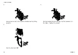
Fig. 4-40
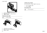
1.
Loosen screws and clamping levers of dual link
adjustment assembly
A
and screws of upper and lower
rotational pivots
B
.
2.
Adjust component to desired position.
3.
Tighten screws and clamping levers.
4.21 Adjusting Trunk Supports
4.21.1 Adjusting Width
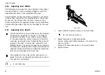
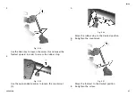
Fig. 4-41
1.
Loosen knobs
A
that hold lateral supports.
2.
Adjust component to desired position.
3.
Tighten knobs.
4.21.2 Adjusting Height
•
5 mm Allen key
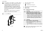
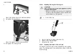
Fig. 4-42
1.
Loosen screws
A
.
2.
Adjust component to desired position.
3.
Tighten screws.
4.21.3 Adjusting Depth
•
5 mm Allen key
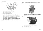
Fig. 4-43
1656515-B
39


