background image

GLOBAL LIMITED WARRANTY (EXCLUDING CANADA)

Part No. 1106645

79

R51™and R51LXP

GLOBAL LIMITED WARRANTY 

(EXCLUDING CANADA)

PLEASE NOTE: THE WARRANTY BELOW HAS BEEN DRAFTED TO COMPLY WITH FEDERAL LAW 

APPLICABLE TO PRODUCTS MANUFACTURED AFTER JULY 4, 1975.

This warranty is extended only to the original purchaser who purchases this product within any country 

excluding CANADA when new and unused from Invacare or a dealer.  This warranty is not extended to any 

other person or entity and is not transferable or assignable to any subsequent purchaser or owner.  

Coverage under this warranty will end upon any such subsequent sale or other transfer of title to any other 

person. For product purchased in Canada, please refer to the Canada Limited Warranty.
This warranty gives you specific legal rights and you may also have other legal rights which vary from state to 

state.

Invacare warrants the base frame to be free from defects in materials and workmanship for a period of three (3) 

years from the date of purchase from Invacare or a dealer, with a copy of the seller’s invoice required for coverage 

under this warranty.   Invacare warrants the seat frame to be free from defects in materials and workmanship for 

a period of three (3) years from the date of purchase from Invacare or a dealer, with a copy of the seller’s invoice 

required for coverage under this warranty.   Invacare warrants all electronics and electrical components 

(excluding batteries), motors and gearboxes to be free from defects in materials and workmanship for a period of 

one (1) year from the date of purchase from Invacare or a dealer, with a copy of the seller’s invoice required for 

coverage under this warranty.  Invacare warrants all batteries to be free from defects in materials and 

workmanship for a period of six (6) months from the date of purchase from Invacare or a dealer, with a copy of the 

seller’s invoice required for coverage under this warranty.  Invacare warrants all remaining components (excluding 

all upholstered materials, padded materials, tires and wheels) to be free from defects in materials and 

workmanship for a period of one (1) year from the date of purchase from Invacare or a dealer, with a copy of the 

seller’s invoice required for coverage under this warranty.  If within such warranty periods any such product 

component shall be proven to be defective, the product component shall be repaired or replaced, at Invacare's 

option. This warranty does not include any labor or shipping charges incurred in replacement part installation or 

repair of any such product. Invacare's sole obligation and your exclusive remedy under this warranty shall be 

limited to such repair and/or replacement.

For warranty service, please contact the dealer from whom you purchased your Invacare product. In the event you 

do not receive satisfactory warranty service, please write directly to Invacare at the address on the bottom of the 

back cover. Provide dealer's name address, date of purchase, indicate nature of the defect and, if the product is 

serialized, indicate the serial number. Do not return products to our factory without our prior consent.

LIMITATIONS AND EXCLUSIONS: THE FOREGOING WARRANTY SHALL NOT APPLY TO SERIAL 

NUMBERED PRODUCTS IF THE SERIAL NUMBER HAS BEEN REMOVED OR DEFACED, PRODUCTS 

SUBJECT TO NEGLIGENCE, ACCIDENT, IMPROPER OPERATION, MAINTENANCE OR STORAGE, 

COMMERCIAL OR INSTITUTIONAL USE, PRODUCTS MODIFIED WITHOUT INVACARE'S EXPRESS 

WRITTEN CONSENT (INCLUDING, BUT NOT LIMITED TO, MODIFICATION THROUGH THE USE OF 

UNAUTHORIZED PARTS OR ATTACHMENTS); PRODUCTS DAMAGED BY REASON OF REPAIRS MADE 

TO ANY COMPONENT WITHOUT THE SPECIFIC CONSENT OF INVACARE, OR TO A PRODUCT 

DAMAGED BY CIRCUMSTANCES BEYOND INVACARE'S CONTROL, AND SUCH EVALUATION WILL BE 

SOLELY DETERMINED BY INVACARE. THE WARRANTY SHALL NOT APPLY TO PROBLEMS ARISING 

FROM NORMAL WEAR AND TEAR OR FAILURE TO ADHERE TO THE PRODUCT INSTRUCTIONS. A 

CHANGE IN OPERATING NOISE, PARTICULARLY RELATIVE TO MOTORS AND GEARBOXES DOES NOT 

CONSTITUTE A FAILURE OR DEFECT AND WILL NOT BE REPAIRED; ALL DEVICES WILL EXHIBIT  

CHANGES IN OPERATING NOISE DUE TO AGING.  

THE FOREGOING EXPRESS WARRANTY IS EXCLUSIVE AND IN LIEU OF ANY OTHER WARRANTIES 

WHATSOEVER, WHETHER EXPRESS OR IMPLIED, INCLUDING THE IMPLIED WARRANTIES OF 

MERCHANTABILITY AND FITNESS FOR A PARTICULAR PURPOSE, AND THE SOLE REMEDY FOR 

VIOLATIONS OF ANY WARRANTY WHATSOEVER, SHALL BE LIMITED TO REPAIR OR REPLACEMENT 

OF THE DEFECTIVE PRODUCT PURSUANT TO THE TERMS CONTAINED HEREIN.  THE APPLICATION 

OF ANY IMPLIED WARRANTY WHATSOEVER SHALL NOT EXTEND BEYOND THE DURATION OF THE 

EXPRESS WARRANTY PROVIDED HEREIN AND INVACARE SHALL NOT BE LIABLE FOR ANY 

CONSEQUENTIAL OR INCIDENTAL DAMAGES WHATSOEVER;  SOME STATES DO NOT ALLOW THE 

EXCLUSION OR LIMITATION OF INCIDENTAL OR CONSEQUENTIAL DAMAGE, OR LIMITATION OF 

HOW LONG AN IMPLIED WARRANTY LASTS, SO THE ABOVE EXCLUSION AND LIMITATION MAY NOT 

BE APPLICABLE.

THIS WARRANTY SHALL BE EXTENDED TO COMPLY WITH STATE/PROVINCIAL LAWS AND 

REQUIREMENTS.

Summary of Contents for Nutron R51

Page 1: ...ual MUST be given to the user of the wheelchair USER BEFORE using this wheelchair read this manual and save for future reference For more information regarding Invacare products parts and services ple...

Page 2: ...contact a health care professional or dealer before attempting to use this equipment DO NOT use this product or any available optional equipment without first com pletely reading and understanding the...

Page 3: ...ON 2 SAFETY GUIDELINES 16 SECTION 3 EMI INFORMATION 19 SECTION 4 SAFETY HANDLING OF WHEELCHAIRS 21 Stability and Balance 21 Coping With Everyday Obstacles 21 A Note to Wheelchair Assistants 22 Tilting...

Page 4: ...Service Indicator 35 Information Gauge Display 35 SECTION 7 FRONT RIGGINGS 36 Installing Removing the Footrests 36 Installing 36 Removing 36 Adjusting the Footrest Height 37 Model PW93 PW93E and PW93S...

Page 5: ...SECTION 12 CASTERS 54 Adjusting Forks 54 SECTION 13 BATTERIES 55 Warnings for Handling and Replacing Batteries 55 Using the Proper Batteries 56 Recommended Battery Types 56 Installing Removing the Ba...

Page 6: ...ing the Wheel Locks 73 Installing Adjusting 73 Using 74 SECTION 16 ANTI TIPPERS 75 Installing Removing the Anti Tippers 75 Installing 75 Removing 75 SECTION 17 TRANSPORTING 76 Transporting the Nutron...

Page 7: ...cle of any type It is Invacare s position that users of wheelchairs should be transferred into appropriate seating in vehicles for transportation and use be made of the restraints made available by th...

Page 8: ...18 inches SEAT TO FLOOR 17 or 19 inches OVERALL WIDTH 21 inches to 27 inches With joystick OVERALL HEIGHT LOW SEAT ADULT 33 inches to 37 inches 35 inches to 39 inches OVERALL LENGTH 36 inches to 47 i...

Page 9: ...care should be exercised when using oxygen in close proximity to electric circuits and other combustible materials Contact your oxygen supplier for instruc tion in the use of oxygen Batteries DANGER W...

Page 10: ...mage to the cord or personal injury to the user or bystanders Ensure the pins of the extension cord plug are the same number size and shape as those on the charger DO NOT under any circumstances cut o...

Page 11: ...s injury or damage Performance adjustments should only be made by professionals of the healthcare field or persons fully conversant with this process and the driver s capabilities After the wheelchair...

Page 12: ...DO NOT shift your weight or sitting position toward the direction you are reaching as the wheelchair may tip over DO determine and establish your particular safety limits by practicing bending reachi...

Page 13: ...that the footplates are in the upward position or swing footrests towards the outside of the chair Anti tippers MUST be used at all times When outdoors on wet soft ground or gravel surfaces anti tippe...

Page 14: ...t of electrical components more frequently Rain Test CAUTION Risk of Damage Operating the wheelchair in rain or dampness may cause the wheelchair to malfunction electrically and mechanically may cause...

Page 15: ...weight training If occupant uses said wheelchair as a weight training appara tus Invacare shall not be liable for bodily injury and the warranty is void Weight Limitation WARNING The Nutron R51 has a...

Page 16: ...ns could cause the wheelchair to suddenly stop resulting in serious injury or damage ALWAYS ensure that all electrical connections are tightly connected so they don t vibrate loose WARNING Risk of Inj...

Page 17: ...ement DANGER Risk of Death or Serious Injury Traveling on inclines with wet slippery icy or oily surfaces could cause loss of traction resulting in death or serious injury DO NOT use on inclines with...

Page 18: ...ious injury DO NOT exceed the weight capacity WARNING Risk of Serious Injury or Death Failure to observe this warning can result in serious injury or death Loss of traction on ramps and inclines can o...

Page 19: ...ection from the more common sources of radiated EMI There are a number of sources of relatively intense electromagnetic fields in the everyday environment Some of these sources are obvious and easy to...

Page 20: ...ate hand held transceivers transmitters receivers such as citizens band CB radios or turn ON personal communication devices such as cellular phones while the powered wheelchair is turned ON 2 Be aware...

Page 21: ...anual are a starting point for the new wheelchair user and assistant with safety as the most important consideration for all Stability and Balance WARNING Be aware that carrying heavy objects on your...

Page 22: ...alone Tilting WARNING DO NOT tilt the wheelchair without assistance When tilting the wheelchair an assistant should grasp the back of the wheelchair on a non removable non detachable part Inform the...

Page 23: ...tween floors by means of a stairway the occupant MUST be removed and transported independently of the power wheelchair Extreme caution is advised when it is necessary to move an unoccupied power wheel...

Page 24: ...ring transfer ALWAYS turn the wheelchair power off ALWAYS engage both motor locks clutches and free wheel hubs if equipped to prevent the wheels from moving before transferring into or from the wheelc...

Page 25: ...le wheel locks WARNING Risk of Serious Injury or Damage Improper positioning while leaning or bending could cause the wheelchair to tip forward resulting in serious injury or damage To assure stabilit...

Page 26: ...tion wheelchair as close as possible to the desired object 2 Point the front casters as far forward as possible to create the longest possible wheelbase 3 Reach back only as far as your arm will exten...

Page 27: ...ms are secure but easy to release and adjustment levers engage properly Ensure adjustable height arms operate and lock securely Ensure arm pivot points are free of wear and looseness Inspect seat and...

Page 28: ...headtube fasteners are secure Inspect for any loose hardware on the wheelchair Inspect seat positioning strap for any signs of wear Ensure buckle latches Verify hardware that attaches strap to frame...

Page 29: ...rted cell Replace if necessary Contact dealer Invacare for service Battery indicator flashes the charge level is low immediately after recharge Battery failure Malfunctioning battery charger Electrica...

Page 30: ...SOLUTION 1 User Fault Release joystick to neutral and try again 2 Battery Fault Charge the batteries Refer to Charging Batteries on page 62 Check that battery cables are connected properly Refer to Di...

Page 31: ...elchair to a work area before cleaning termi nals or opening battery box Don t make it a habit to discharge batteries to the lowest level Recharge as frequently as possible to maintain a high charge l...

Page 32: ...d injury or damage may occur NOTE For this procedure refer to FIGURE 6 2 The joystick is located on the joystick housing and provides smooth control of speed and direction It is equipped with 360 degr...

Page 33: ...hes and Indicators MOVEMENT ACTION FORWARD Push joystick forward towards the front of the wheelchair REVERSE Pull joystick back towards the rear of the wheelchair Turn RIGHT Move joystick toward the r...

Page 34: ...Adjust Speed in 20 Increments 5 Speed Mode Press the tortoise button or hare button to decrease increase the speed in 20 increments The larger bars in the speedometer will light Adjust Speed in Small...

Page 35: ...nt of the joystick housing it provides the following information to the user on the status of the wheelchair 1 Power is on 2 True state of battery charge including notification of when the battery req...

Page 36: ...talling Removing the Footrests NOTE For this procedure refer to FIGURE 7 1 Installing 1 Turn footrest to the side open footplate is perpendicular to wheelchair and position mounting holes in the footr...

Page 37: ...ests on page 36 NOTE Lay footrest on a flat surface to simplify procedure 3 Remove the hex bolt coved washers and locknut that secure the lower footrest to the footrest support 4 Reposition the lower...

Page 38: ...rt No 1106645 FIGURE 7 2 Adjusting the Footrest Height Model PW93 PW93E and PW93ST Footrests Footrest Support Coved Washer Hex Bolt Locknut Coved Washer Lower Footrest NOTE PW93ST style footrest shown...

Page 39: ...7 4 1 Note the position of hex bolt coved washers and locknut for reinstallation 2 Remove the hex bolt coved washers and locknut that secure the lower footrest to the footrest support 3 Remove the lo...

Page 40: ...Legrests 5 After seated in wheelchair adjust footplate to correct height by loosening nut and sliding the lower footrest assembly up or down until desired height is achieved Removing 1 Push the legre...

Page 41: ...ating Legrests and or Adjusting Calfpads Adjusting Replacing Telescoping Front Rigging Support NOTE For this procedure refer to FIGURE 7 7 on page 42 NOTE When adjusting the telescoping front rigging...

Page 42: ...ide of the wheelchair when locked in place 5 Using the front and rear socket bolts and two locknuts secure the telescoping front rigging support to the wheelchair frame as shown in FIGURE 7 7 6 Using...

Page 43: ...using the wheelchair 1 Unlock the armrest by flipping the height adjustment lever on the top front of the armrest to the up horizontal position 2 Adjust armrest to one of five positions NOTE Height a...

Page 44: ...sockets 4 Lock the swing back arms by rotating the armrest release lever toward the inside of the wheelchair FIGURE 8 2 Using Swing Back Arms Replacing Desk Full Length Armrest Pad and or Clothing Gu...

Page 45: ...utside of the wheelchair 2 Lift armrest completely out of arm sockets from the wheelchair Installing NOTE Armrest release levers MUST be in the unlocked position when placing armrests into the arm soc...

Page 46: ...back canes use four mounting screws 1 Remove the mounting screws and locknuts that secure the two back canes to the back cane mounting tube 2 Reposition the back canes to the desired height adjustment...

Page 47: ...er to FIGURE 9 3 on page 48 WARNING The following procedure must be performed by a qualified technician The seat depth and back angle of the wheelchair as well as the large wheel position directly rel...

Page 48: ...securely tighten with locknut Refer to FIGURE 9 3 for correct hardware orientation 5 Securely tighten the rear hex screw that secures the back adjustment plate to the wheelchair frame FIGURE 9 3 Chang...

Page 49: ...ers NOTE Clean upholstery with warm DAMP cloth and mild detergent to remove superficial soil FIGURE 10 1 Replacing Seat Upholstery WARNING Laundering or moisture will reduce flame retardation of the u...

Page 50: ...n from the seat upholstery 2 Remove the two rear phillips screws and washers that secure the seat upholstery and seat positioning strap to the crossbraces 3 Remove the two halves of the seat positioni...

Page 51: ...SECTION 10 UPHOLSTERY SEAT POSITIONING STRAP Part No 1106645 51 R51 and R51LXP FIGURE 10 3 Replacing Seat Positioning Strap Washer Rear Phillips Screw Seat Upholstery Crossbrace Seat Positioning Strap...

Page 52: ...f the wheelchair To reposition the joystick onto the left side of the wheelchair refer to Repositioning the Joystick on page 53 The joystick should be repositioned by a qualified technician 1 Turn the...

Page 53: ...m tube ensuring the threaded plate of the mounting bracket is on the inside of the arm tube as shown in FIGURE 11 2 5 Using the three hex mounting screws and washers secure the halves of the mounting...

Page 54: ...tube hardware Refer to Adjusting Replacing Telescoping Front Rigging Support on page 41 1 Remove the dust cover from the caster headtube 2 To properly tighten caster journal system and guard against f...

Page 55: ...rvice and BEFORE use make sure that all attaching hardware is tightened securely otherwise injury or damage may result Make sure power to the wheelchair is off before performing this section The use o...

Page 56: ...E 13 1 Using the Proper Batteries Recommended Battery Types WARNING The warranty and performance specifications contained in this manual are based on the use of deep cycle gel cell batteries Invacare...

Page 57: ...WARNING NEVER unplug the battery cables by pulling on the wires Unplug the battery cables by pulling on the connector ONLY Otherwise injury or damage may result NOTE For this procedure refer to FIGUR...

Page 58: ...ity NOTE For these procedures refer to FIGURE 13 3 on page 59 NOTE To remove the battery tray from the wheelchair reverse the following procedure 16 18 and 20 Inch Wide Wheelchair 14 Inch Wide Wheelch...

Page 59: ...n and battery replacement ALWAYS be done by a qualified technician After ANY adjustments repair or service and BEFORE use make sure all attaching hardware is tightened securely otherwise injury or dam...

Page 60: ...inal post 1 If necessary remove the battery boxes from the wheelchair Refer to Installing Removing the Battery Boxes on page 57 2 Secure the battery lifting strap to battery terminal s post s CAUTION...

Page 61: ...Post s Use direct mount method Refer to FIGURE 13 5 and FIGURE 13 6 Dual Group 22NF Batteries without Mounting Holes in the Terminal s Post s Use battery clamp method Refer to FIGURE 13 7 FIGURE 13 8...

Page 62: ...ACK to NEGATIVE and RED to POSITIVE with the provided 1 4 20 x 7 8 inch hex flange screw and hex flange locknut as shown in Detail A or Detail B of FIGURE 13 6 depending on battery type Securely tight...

Page 63: ...T Tie Wraps GREY Battery Terminal Cap NEGATIVE Battery Terminal Post POSITIVE Battery Terminal Post ORANGE Battery Terminal Cap Detail B Dual Group 22 NF Batteries 1 4 20 X 7 8 Inch Hex Flange Screw P...

Page 64: ...nut that secures the battery clamp to the POSITIVE battery terminal post CAUTION When tightening the clamps always use a box wrench Pliers will round off the nuts NEVER wiggle the battery terminal s p...

Page 65: ...OSITIVE RED battery cable ring terminal between the mounting plate and battery clamp of POSITIVE battery terminal post 4 Secure the battery cable s ring terminal s to the battery clamp s BLACK to NEGA...

Page 66: ...Cover Detail B POSITIVE Terminal Post NEGATIVE Terminal Post Group 22NF Battery Clamp Mounting Plate Hex Screw POSITIVE RED Cable NEGATIVE BLACK Cable NOTE Clamps exploded for clarification purposes...

Page 67: ...the battery box retaining strap buckle as shown in FIGURE 13 10 NOTE Observe the position and orientation of the battery box retaining strap as it passes through the slots of the battery tray and the...

Page 68: ...with cool water In serious cases or if eye contact is made seek medical attention immediately NEVER smoke or strike a match near batteries If the caps of the battery cells are removed NEVER look direc...

Page 69: ...NOT attempt to recharge the batteries and operate the power wheelchair at the same time DO NOT attempt to recharge the batteries when the wheelchair has been exposed to ANY type of moisture DO NOT at...

Page 70: ...ill stay illuminated for a longer period of time followed by a shorter off time NOTE If performing the charging procedures independently READ and CAREFULLY follow the individual instructions for each...

Page 71: ...an attendant to maneuver the wheelchair without power To engage disengage the clutches 1 Locate the clutch handles on motors as shown in FIGURE 14 1 CAUTION If clutch handles are forced to engage in...

Page 72: ...the power is in the off position NOTE For this procedure refer to FIGURE 14 2 NOTE Motor lock disengagement engagement allows free wheeling or joystick controlled operation Free wheeling allows an as...

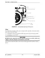
Page 73: ...d psi on the side wall of tire NOTE If necessary remove threaded plastic insert from the wheel lock mounting hole in the wheelchair frame 1 Position the wheel lock on the wheelchair frame 2 Loosely in...

Page 74: ...age the wheel locks grip the handle and push forward to the lock position 2 To disengage reverse STEP 1 CAUTION DO NOT use the wheel locks when the wheelchair power is on and the clutches are engaged...

Page 75: ...ces anti tippers may not provide the same level of protection against tipover Extra caution must be observed when traversing such surfaces NOTE For this procedure refer to FIGURE 16 1 Installing 1 Pre...

Page 76: ...NING Keep hands and fingers clear of moving parts to avoid injury DO NOT place hand or fingers on the underside of the seat rail when opening or closing the wheelchair DO NOT sit or transfer into the...

Page 77: ...he Nutron Refer to Installing Removing the Battery Boxes on page 57 and Installing Removing the Battery Tray on page 58 Refer to Installing Removing the Anti Tippers on page 75 Refer to Installing Rem...

Page 78: ...Refer to the Inspection Checklists in this manual for proper preventative maintenance schedule This is just a general guideline and does not include items damaged due to abuse and misuse PRODUCT TYPE...

Page 79: ...ed at Invacare s option This warranty does not include any labor or shipping charges incurred in replacement part installation or repair of any such product Invacare s sole obligation and your exclusi...

Page 80: ...e contact the dealer from whom you purchased your Invacare product In the event you do not receive satisfactory warranty service please write directly to Invacare at the address on the bottom of the b...

Reviews: