SECTION 13—ELECTRONICS
Part No. 1125075
125
Pronto® Series
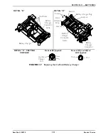
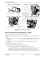
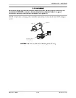
FIGURE 13.5
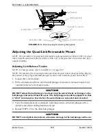
Adjusting Lock/Release Tension
Replacing the Controller
WARNING
DO NOT attempt to perform this procedure with any power supplied to the wheel
chair. The joystick and batteries MUST be disconnected prior to beginning to
remove the controller module. Otherwise, equipment damage and/or personnel
injury may occur.
NOTE: For this procedure, refer to FIGURE 13.6 on page 126.
NOTE: There are four cables connected to the MK5-NX controller module. There are five cables
connected to the MK5-NX w/ACC or MK660 w/ACC controller module. These cables must be
disconnected before the controller can be removed.
NOTE: Take note of position and orientation of the controller, cables, connectors and mounting
hardware for reinstallation of controller.
1. Remove the seat. Refer to one of the following procedures:
• Van Seats - Refer to Removing/Installing the Seat Assembly on page 50.
• ASBA Seats - Refer to Removing/Installing the Seat Assembly on page 59.
2. Remove the top shroud. Removing/Installing the Top Shroud on page 87.
3. Remove the front battery from the wheelchair. Refer to Removing/Installing Batteries
from/into Battery Tray on page 99.
4. Remove the front shroud. Refer to Removing/Installing the Front Shroud on page 89.
5. Remove the footboard. Refer to Removing/Installing the Footboard Assembly on
page 78.
6. Disconnect the right and left motor leads from the controller (Detail “A” or Detail “B”).
Arm
Quad Link Retractable Mount
Joystick
Bottom View
Ball Plunger
Locknut

