background image

SECTION 8—FRONT RIGGINGS/FOOTBOARD

Part No. 1125075

79

Pronto® Series

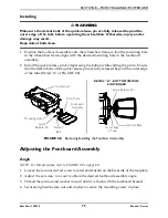
Installing


WARNING

Make sure the detent balls of the quick-release pin are fully released beyond the 

outer edge of the tube before operating the wheelchair. Otherwise, injury and/or 

damage may result.
Keep detent balls clean.

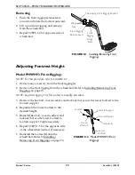
1. Position the footboard assembly onto the wheelchair frame so that the mounting hole 

in the wheelchair frame aligns with the desired mounting hole in the footboard 

assembly.

2. Install the quick release pin by depressing the button while sliding the pin in. Ensure 

that the detent balls of the quick release pin are fully released beyond the outer edge 

of the tube (Detail “A” of FIGURE 8.8).

FIGURE 8.8   

Removing/Installing the Footboard Assembly

Adjusting the Footboard Assembly

Angle

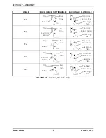
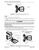
NOTE: For this procedure, refer to FIGURE 8.9 on page 80.

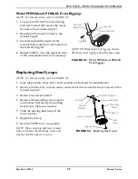
1. Loosen the jam nut and set screw located underneath on the backside of the footplate.
2. Adjust the set screw in or out to obtain the desired footboard assembly angle.
3. Thread the jam nut and washer inward until it is flush with the footboard bracket.
4. Securely tighten the jam nut and washer to secure the mounting screw in place.

DETAIL “A” - BOTTOM VIEW OF 

FOOTBOARD

Quick 

Release Pin

Detent 

Ball

Footboard 

Assembly

Mounting Hole

Top Shroud

Quick Release Pin

Outer Edge 

of Tube

Detent Balls

Pinch Point

Summary of Contents for Pronto M50

Page 1: ...LER Keep this manual The procedures in this manual MUST be performed by a qualified technician For more information regarding Invacare products parts and services please visit www invacare com Pronto...

Page 2: ...S EQUIPMENT OTHERWISE INJURY OR DAMAGE MAY RESULT RECOMMENDED TOOLS The following tools are recommended for servicing this wheelchair Invacare Power Mobility Field Service Kit p n 1125222 5mm ball hea...

Page 3: ...rs 20 Troubleshooting 20 Wheels 20 About Joystick Diagnostics 20 SPJ Information Gauge Display Diagnostics 21 SPJ Information Gauge Display Diagnostics 22 Diagnostic Codes 23 Motor Gearbox Brake 25 Ba...

Page 4: ...rm 44 Adjusting Van Seat Arm Width 44 Adjusting Van Seat Arm Angle 45 Adjusting Van Seat Arm Height Adjustable Height Arms Only 45 Replacing Van Seat Armrest Assembly 46 Removing Installing Flip Back...

Page 5: ...ngs 74 Model PH904A and PHAL4A Front Riggings 75 Replacing Heel Loops 75 Raising Lowering Elevating Front Riggings 76 Adjusting Replacing Telescoping Front Rigging Supports 76 Van Seats 76 ASBA Seat 7...

Page 6: ...ensor 97 Removing 97 Installing 97 SECTION 11 BATTERIES 98 Warnings For Handling and Replacing Batteries 98 Using the Proper Batteries 99 Removing Installing Batteries from into Battery Tray 99 Removi...

Page 7: ...ecting the Joystick 123 Disconnecting 123 Connecting 123 Adjusting the Quad Link Retractable Mount 124 Adjusting Lock Release Tension 124 Replacing the Controller 125 Wire Routing 127 SECTION 14 ACCES...

Page 8: ...It is Invacare s position that users of wheelchairs should be transferred into appropriate seating in vehicles for transportation and use be made of the restraints made available by the auto industry...

Page 9: ...own ramps at high speed Doing so will reduce traction and increase stopping distance The end user s weight can materially affect traction on sloped surfaces Great care should be taken when traversing...

Page 10: ...Pronto Series 10 Part No 1125075 LABEL LOCATION The serial number label is located inside of the front frame The top shroud and front battery need to be removed to view the label M50 M51 Wheelchairs M...

Page 11: ...FRONT RIGGINGS M50 M51 WITH ELEVATING SEAT M61 20 to 24 inches 22 to 24 inches 21 23 inches up to 5 inches of Elevate 19 to 23 inches 19 23 inches 19 to 21 inches up to 5 inches of Elevate 17 21 inche...

Page 12: ...erall terrain conditions will result in actual values for range that differ from these stated values Users should become accustomed to how their unique conditions impact their individual results Users...

Page 13: ...ion should be replaced IMMEDIATELY Wheelchairs that are used by incontinent users and or are frequently exposed to water may require replacement of electrical components more frequently Operation Info...

Page 14: ...the joystick is in the Off position Avoid storing or using the wheelchair near open flame or combustible products Serious injury or damage to property may result ALWAYS keep hands and fingers clear of...

Page 15: ...y charger and an independent battery charger plugged into the joystick charger port at the same time Doing so will reduce the life of the batteries Read and carefully follow the manufacturer s instruc...

Page 16: ...maturely rust and or may damage the upholstery Check to ensure that the RED and GREY battery terminal caps are secured in place joystick boot is not torn or cracked where water can enter and that all...

Page 17: ...ection from the more common sources of radiated EMI There are a number of sources of relatively intense electromagnetic fields in the everyday environment Some of these sources are obvious and easy to...

Page 18: ...te hand held transceivers transmitters receivers such as citizens band CB radios or turn ON personal communication devices such as cellular phones while the powered wheelchair is turned ON 2 Be aware...

Page 19: ...o wheelchair frame Ensure seat release latch is functional Replace if necessary Clean upholstery and armrests Ensure no excessive side movement or binding occurs when drive wheels are lifted and spun...

Page 20: ...l troubleshooting information and explanation of error codes refer to the individual electronics manual supplied with each wheelchair Wheels About Joystick Diagnostics The joystick information gauge a...

Page 21: ...es reduced battery charge Left RED LED is flashing Battery charge is low The batteries should be charged as soon as possi ble Left to Right chase alter nating with steady display Joystick is in progra...

Page 22: ...t to Right chase alternating with steady display Joystick is in programming inhibit and or charging mode The steady LEDs indicate the current state of the battery charge GREEN LED is flashing Joystick...

Page 23: ...ort Circuit Check the left motor connections and motor cable 01 Left Motor Open Circuit 02 Left Motor Connection Fault B 03 Motor Terminal Connected to B 04 Left Motor Voltage Fault 05 Left Motor Brid...

Page 24: ...ark Brake Fault 00 Right Park Brake Drive Time Test Failed Check the right park brake connections and cable 01 Right Park Brake Output Enabled When Wheelchair Idle 02 Right Park Brake Output Did not E...

Page 25: ...al Service 11 E11 Incompati ble incorrect Remote 00 Incompatible incorrect Remote Wrong type of remote connected Ensure the branding of the joystick matches that of controller unit SYMPTOM PROBABLE CA...

Page 26: ...haft Loose hardware If seal is bad replace motor gearbox Remove motor brushes and inspect for grease contamination Replace motor gearbox if contamination is found Refer to Replacing Motor Brushes on p...

Page 27: ...to Invacare for repair Refer to Replacing the Controller on page 125 Motor runs but loses power Controller senses heavy load and has entered the current rollback mode Stop driving and let electronics...

Page 28: ...volt meter Damaged power cord Check for damage on the power cord replace if damaged or send to Invacare for repair Charger LED s burnt out Send charger to Invacare for repair Charger may have interna...

Page 29: ...nsor Replace if necessary Refer to Removing Installing the Actuator Switch Sensor on page 97 DO DON T Read and understand this manual and any service information that accompanies a battery and charger...

Page 30: ...as a bad one 3 Remove the footrests from the wheelchair Refer to Front Riggings FootBoard on page 73 4 Connect the voltmeter leads to the charger port on the wheelchair as shown in FIGURE 3 1 Most di...

Page 31: ...ital multimeter to measure resistance ohms 3 Measure the resistance between the two motor contacts NOTE A normal reading is between 5 and 5 ohms A reading of 0 ohms or in excess of 15 ohms indicates a...

Page 32: ...ing the On Off switch up or down The switch automatically retracts back to center position NOTE After turning power On all indicators will light briefly and the display gauge will indicate one of the...

Page 33: ...he joystick The LEDs will flash briefly and the horn will sound a short beep Using the Joystick to Drive the Wheelchair WARNING DO NOT operate wheelchair on an incline while in an elevated position Ot...

Page 34: ...djusting the Speed on page 35 3 Maneuver the joystick in the following manner FIGURE 4 3 Using the Joystick to Drive the Wheelchair MOVEMENT ACTION FORWARD Push forward on the joystick REVERSE Pull ba...

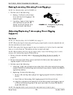
Page 35: ...Perform one of the following Adjust Speed in 20 Increments 5 Speed Mode Press the tortoise button or hare button to decrease increase the speed in 20 increments The larger bars in the speedometer will...

Page 36: ...lchairs Manufactured Before 8 15 05 NOTE For this procedure refer to FIGURE 4 6 1 Press the horn button located above the information gauge on the joystick housing FIGURE 4 6 Using the Horn M50 and M5...

Page 37: ...object such as a table or desk Use only the MK5 NX w ACC or MK660 w ACC controller to activate the elevate function DO NOT use any other actuator controls Such devices may result in excess heating and...

Page 38: ...y 1 Make sure the wheelchair is on a level surface 2 Press the mode button to switch from driving mode to elevate mode NOTE The LED will light up with a circle around it 3 Move the joystick Forward El...

Page 39: ...the speed of the wheelchair 2 Turn the switch counterclockwise to decrease the speed of the wheelchair Joystick The joystick has proportional drive control meaning that further the wheelchair is pushe...

Page 40: ...EN LED is lit indicating well charged batteries B Only AMBER LEDs are lit indicating batteries are moderately charged Recharge batteries before taking a long trip C Only RED LED is lit indicating batt...

Page 41: ...irs FIGURE 4 10 SPJ and SPJ w ACC Joystick Switches and Indicators On Off Button DETAIL A FRONT VIEW Charger Progra mming Input Speedometer Joystick GREEN LED Information Gauge Display Service Indicat...

Page 42: ...nd adjust the maximum speed 1 To adjust the speed perform one of the following Adjust Speed in 20 Increments 5 Speed Mode Press the tortoise button or hare button to decrease increase the speed in 20...

Page 43: ...vice Indicator The AMBER service indicator will light when an error or fault occurs Refer to electronics manual supplied with wheelchair Information Gauge Display Located on the front of the joystick...

Page 44: ...dth arm from the arm support tube 4 If necessary repeat STEPS 1 3 to remove the remaining adjustable width arm Adjusting Van Seat Arm Width WARNING Increasing the width of the arms may affect the over...

Page 45: ...Tighten the jam nut 5 To determine the same angle for the opposite armrest count the exposed threads after the jam nut has been tightened 6 Repeat STEPS 1 5 for opposite armrest if necessary Adjusting...

Page 46: ...he arm post 3 Position the new armrest assembly on the armrest post and secure with the mounting screw washers and locknut Refer to FIGURE 5 3 for correct hardware orientation 4 If necessary install t...

Page 47: ...armrest 1 If necessary disconnect the joystick Disconnecting Connecting the Joystick on page 123 2 Unlock flip back armrest by pulling flip back armrest release lever into the unlocked horizontal posi...

Page 48: ...stment lever into the up horizontal position 2 Adjust top of the flip back armrest to the desired height 3 Lock top of flip back armrest by pushing height adjustment lever into the down vertical posit...

Page 49: ...seat to desired angle 2 Let go of the release handle to lock the back in position FIGURE 6 1 Adjusting the Back Angle Semi Recline Back Angle Fold Down Back Angle NOTE For this procedure refer to FIGU...

Page 50: ...tion FIGURE 6 3 Adjusting the Headrest Semi Recline Only Removing Installing the Seat Assembly NOTE For this procedure refer to FIGURE 6 4 on page 51 Removing 1 Disconnect the joystick Refer to Discon...

Page 51: ...E 6 5 on page 52 1 Remove the seat Refer to Removing Installing the Seat Assembly on page 50 2 Perform one of the following For Standard Van Seat i Remove the seat base from the seat assembly Refer to...

Page 52: ...Refer to Adjusting Seat Position on Seat Base on page 56 7 Reinstall the seat Refer to Removing Installing the Seat Assembly on page 50 FIGURE 6 5 Adjusting Seat Depth Mounting Holes Mounting Screws S...

Page 53: ...n FIGURE 6 8 on page 57 for proper seat post mounting positions For users over 220 lbs Mounting holes 3 4 and 5 in FIGURE 6 6 MUST be used with the seat in the 1 inch back position FIGURE 6 8 Refer to...

Page 54: ...ith four 1 inch spacers secured by either 3 inch or 3 inch mounting screws 1 inch 2 inch and 2 inch mounting screws are supplied with the seat For Seat Height Reduced by One Inch i Align the mounting...

Page 55: ...61 Wheelchairs Washers Mounting Screws NOTE Three inch and three and a half mounting screws shown One inch and two inch mounting screws are supplied with the seat Seat Pivot 1 inch Adjustment Spacers...

Page 56: ...Remove the seat Refer to Removing Installing the Seat Assembly on page 50 2 Remove the four mounting screws and washers securing the seat pivot to the seat base FIGURE 6 8 3 Separate the seat pivot fr...

Page 57: ...L A SEAT POSITION I inch Back Seat Position I inch Back Seat Position I inch Back Seat Position Standard Seat Position Standard Seat Position Standard Seat Position Standard Seat Position Front of Sea...

Page 58: ...dure refer to FIGURE 6 9 1 Remove the two mounting screws that secure the seat positioning straps to the seat frame 2 Remove the two halves of the seat positioning strap from the rear seat frame 3 Rep...

Page 59: ...re refer to FIGURE 7 1 on page 60 Removing 1 Disconnect the joystick Refer to Disconnecting Connecting the Joystick on page 123 2 Fold down the seat back 3 Pull the seat lever up and lift the seat ass...

Page 60: ...e seat Refer to Removing Installing the Seat Assembly on page 59 2 Remove the mounting screw that secures the seat post to the support tube WARNING Refer to the table in FIGURE 7 2 on page 61 for prop...

Page 61: ...ight M50 51 Wheelchairs Only WEIGHT LIMITATION SEAT POST MOUNTING HOLE SEAT DEPTH 1 INCH BACK STANDARD 1 INCH FORWARD 300 LBS 1 Y Y N A 2 Y Y N A 3 Y N A N A 4 Y N A N A 5 Y N A N A 220 LBS 1 Y Y Y 2...

Page 62: ...ght by 2 Inches Remove both sets of 1 inch adjustment spacers to achieve desired height 4 Perform one of the following NOTE The seat comes installed with four spacers secured by 3 inch mounting screws...

Page 63: ...nufacturers seating system installation instructions Remove cushion by pulling up to release hook and loop strips Remove cushion from seat pan 2 Remove the two rear mounting screws quick release pin t...

Page 64: ...lled in the accessory tube Refer to Accessories on page 128 2 Remove the arms Refer to Removing Installing Flip Back Armrest on page 47 3 Remove the four hex screws and locknuts securing the seat fram...

Page 65: ...mounting screws washers and locknuts securing the seat frame plate and 1 inch adjustment spacers to the seat pivot NOTE M61 wheelchairs may have up to two sets of 1 inch adjustment spacers between th...

Page 66: ...to the seat frame 4 Remove the two halves of the seat positioning strap from the rear seat frame 5 Reposition the two new seat positioning strap halves underneath seat rails 6 Reinstall the two mount...

Page 67: ...re and inserts will be reused NOTE Take note of position and orientation of mounting hardware for reinstallation Removing 1 Remove flip back armrest from the wheelchair Refer to Removing Installing Fl...

Page 68: ...bar to the back canes 11 Grasp the hand grip and slide the back cane out of the spreader bar if applicable and the back upholstery Installing NOTE If replacing back upholstery discard existing back up...

Page 69: ...FIGURE 7 8 Use Loctite 242 and torque to 75 inch lbs 9 Repeat STEPS 6 8 on opposite side of wheelchair 10 Secure the top of the back upholstery to the back canes with the two existing mounting screws...

Page 70: ...ut Spreader Bar Back Insert NOTE When replacing the back upholstery back assembly or changing back height follow these guidelines for spreader bar height NOTE Height of spreader bar from bottom of bac...

Page 71: ...gh the cane from the inside of wheelchair to hold the insert in place 3 Remove the mounting screw washer coved washer and locknut from the bottom mounting hole of the back angle plate and back cane 4...

Page 72: ...80 85 90O 95 100 Top Bottom Back Cane Top Front Bottom Rear Back Angle Plate Top 2nd From Bottom Back Cane Top Front Bottom Center Back Angle Plate Top Bottom Back Cane Top Front Bottom Front Back An...

Page 73: ...off the side of the footboard they may come in contact with the caster possibly resulting in injury Installing Removing Front Riggings CAUTION If front riggings are used then the seat MUST be adjuste...

Page 74: ...ings on page 73 NOTE Lay front rigging on a flat surface to simplify procedure 3 Remove the hex bolt coved washers and locknut that secure the lower footrest to the footrest support 4 Reposition the l...

Page 75: ...E 8 4 1 Note the position of hex bolt coved washers and locknut for reinstallation 2 Remove the hex bolt coved washers and locknut that secure the lower footrest to the footrest support 3 Remove the l...

Page 76: ...s not affect seat depth NOTE When installing the front rigging support tubes ensure that the hinge pins are on the outside of the chair facing away from the seat frame 1 Remove the seat assembly Refer...

Page 77: ...this procedure refer to FIGURE 8 7 on page 78 1 Remove the two mounting screws spacers and locknuts that secure the telescoping front rigging support to the seat frame 2 Perform one of the following...

Page 78: ...gging Supports Removing Installing the Footboard Assembly WARNING Pinch point may occur when rotating the footboard assembly NOTE For this procedure refer to FIGURE 8 8 on page 79 Removing 1 Remove th...

Page 79: ...detent balls of the quick release pin are fully released beyond the outer edge of the tube Detail A of FIGURE 8 8 FIGURE 8 8 Removing Installing the Footboard Assembly Adjusting the Footboard Assembly...

Page 80: ...he wheelchair Otherwise injury and or damage may result Keep detent balls clean 2 Adjust footboard to one of three mounting positions 3 Install the quick release pin Make sure the detent balls of the...

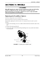
Page 81: ...eplacing the Front Rear Casters NOTE For this procedure refer to FIGURE 9 1 NOTE Front and rear casters are replaced in the same manner NOTE When replacing the front rear casters it is necessary to br...

Page 82: ...Pivot both caster assemblies to top of their arc simultaneously C Let casters drop to bottom of arc casters should swing once to one side then IMMEDIATELY rest in a straight downward position D Adjust...

Page 83: ...ng the Front Headtube Assembly NOTE For this procedure refer to FIGURE 9 3 NOTE Take note of position and orientation of headtube and mounting hardware for installation NOTE Reverse this procedure to...

Page 84: ...t Applying more than one inch in length can cause the anti seize compound to leak resulting in damage to flooring carpet tile etc 1 Apply an anti seize compound to drive shaft and keystock 2 Align the...

Page 85: ...isting mounting screws locknuts and washers that secure the existing outer rim and inner rim 3 Separate the two halves of the rim and remove the existing tire Discard existing tire NOTE When installin...

Page 86: ...the outer rim to the inner rim and hub Torque hex nuts to 160 200 inch lbs 7 If pneumatic fill tire to correct air pressure as noted on tire side wall FIGURE 9 5 Replacing the 2 Piece Wheel Rim and o...

Page 87: ...on page 88 Removing 1 Disconnect the joystick Refer to Disconnecting Connecting the Joystick on page 123 2 M61 Wheelchairs Only Remove the joystick cable from the clip on the top shroud 3 Remove the s...

Page 88: ...roud to the frame 2 Remove the side shroud from the frame Installing 1 Position the side shroud onto the frame 2 Align the shroud mounting holes with the mounting holes in the frame 3 Secure the side...

Page 89: ...URE 10 3 on page 90 Removing 1 Remove the two screws securing the top of the front shroud to the frame 2 Remove the front shroud fo the frame Installing 1 Insert the tabs at the bottom of the front sh...

Page 90: ...ng beam 3 Remove the small screw securing the the inner shroud to the side shroud if present 4 Remove the inner shroud Installing 1 Position the inner shroud on the walking beam 2 Use the small screw...

Page 91: ...ront Headtube Assembly on page 83 2 Remove the side shroud Refer to Removing Installing the Side Shrouds on page 88 3 remove the locknut two small washers and large washer securing the rear of the piv...

Page 92: ...el to the end of the walking beam If necessary reposition the pivot tube 3 Secure the end of the pivot tube to the pivot post using the two small washers the large washer and the locknut Torque to 90...

Page 93: ...Spring Removing Installing the Walking Beam NOTE For this procedure refer to FIGURE 10 7 on page 94 Removing 1 Remove the front headtube assembly Refer to Removing Installing the Front Headtube Assemb...

Page 94: ...ing Installing the Seat Assembly on page 50 ASBA Seats Refer to Removing Installing the Seat Assembly on page 59 2 Remove the batteries Refer to Removing Installing Batteries from into Battery Tray on...

Page 95: ...the bottom of the frame using the four hex screws and washers Torque to 75 in lbs 20 4 Connect the actuator connector to the controller connector Detail A 5 Secure the cables to the frame using three...

Page 96: ...RE 10 8 Removing Installing the Elevate Actuator Hex Screw Washer Frame Actuator Mounting Holes Button Screw Washer Screw Actuator Switch Sensor Small Washer Elevate Actuator Washer Button Screw DETAI...

Page 97: ...g the Seat Assembly on page 59 3 Remove the batteries Refer to Removing Installing Batteries from into Battery Tray on page 99 4 Remove the two screws and small washers securing the actuator switch se...

Page 98: ...ow any of your tools and or battery cables to contact both battery posts at the same time An electrical short may occur and serious personal injury or damage may occur The POSITIVE battery cable MUST...

Page 99: ...h terminal configuration as shown below MUST be used Batteries that have the reverse terminal configuration MUST NOT be used otherwise injury and damage may occur FIGURE 11 1 Using the Proper Batterie...

Page 100: ...o Removing Installing the Seat Assembly on page 59 4 Remove the top shroud Refer to Removing Installing the Top Shroud on page 87 5 Disconnect the front battery from the controller BLACK connector 6 D...

Page 101: ...e may occur Connect same color connectors to each other RED to RED BLACK to BLACK DO NOT remove fuse or mounting hardware from POSITIVE battery cable mounting screw To replace the fuse obtain and repl...

Page 102: ...to FIGURE 11 3 on page 103 1 Secure the battery cables to the battery terminals as described below Securely tighten Refer to Detail A of FIGURE 11 3 A Secure NEGATIVE battery cable to the NEGATIVE bat...

Page 103: ...knuts U1 Battery POSITIVE Battery Terminal Cap DETAIL A DETAIL B NOTE Handles on batteries removed for clarity POSITIVE Battery Terminal NEGATIVE Battery Terminal Tie wraps U1 Battery U1 Batteries BLA...

Page 104: ...URE 11 3 5 Disconnect POSITIVE battery cable from the POSITIVE battery terminal FIGURE 11 3 6 Disconnect NEGATIVE battery cable from NEGATIVE battery terminal FIGURE 11 3 Charging Batteries WARNING NE...

Page 105: ...battery is low the charge rate is high As a charge builds up the charge rate is reduced and the battery charger rate decreases to a trickle charge NOTE If the batteries need to be charged more often...

Page 106: ...r Open rear shroud to view indicator lights NOTE If the batteries are completely discharged the charger will not charge them Replace the batteries Refer to Removing Installing Batteries from into Batt...

Page 107: ...arger plugged into the joystick charger port at the same time Doing so will reduce the life of the batteries CAUTION Only use a charger approved by Invacare when charging through the joystick on this...

Page 108: ...jury may occur DO NOT attempt to remove the battery charger fuse with power applied to the wheelchair Otherwise equipment damage and or personnel injury may occur NOTE For this procedure refer to FIGU...

Page 109: ...harger on page 109 FIGURE 11 6 Replacing the On Board Battery Charger Fuse Replacing the On Board Battery Charger WARNING DO NOT replace the battery charger fuse with anything other than a 250V 4 Amp...

Page 110: ...existing charger 8 Install the hook and loop strips onto the underside of the new charger 9 Place the new battery charger against the wheelchair frame ensuring that the hook and loop strips properly e...

Page 111: ...Charger Battery Charger Connector Cable Tie Wraps Hook andLoop Strip DETAIL A DETAIL B Battery Charger Plug Locknut Screws Locknut Battery Charger Connector Cable Battery Charger Connector Bracket Pi...

Page 112: ...on page 99 3 Remove the drive wheel Refer to Removing Installing the Drive Wheel on page 84 4 Remove the side shroud Refer to Removing Installing the Side Shrouds on page 88 5 Remove the front shroud...

Page 113: ...Removing Installing the Motor Three Short and Three Long Mounting Screws Motor NOTE Drive wheel shown exploded from the motor drive shaft for clarity Drive Wheel Drive Shaft Walking Beam Motor Lead NO...

Page 114: ...ndles on the motors protruding through the top shroud on the rear of the wheelchair 2 Perform one 1 of the following To Disengage the Motor Release Levers Pull the motor lock lever towards the rear of...

Page 115: ...e motor release lever 3 Remove the cotter pin washer and mounting pin securing the motor lock to the motor release lever Set cotter pin and mounting pin aside Detail A 4 Grasp the motor release lever...

Page 116: ...retainer is not available as a service part 6 Release the tension on the brush spring retainer with a small screwdriver and position the screwdriver in place to hold the spring retainer Refer to Detai...

Page 117: ...ST be performed with little or no load on the motor A Put the wheelchair on blocks so that the drive wheels do not contact the ground NOTE For steps B and D use a rubber band to hold the driver contro...

Page 118: ...ormal reading is between 45 100 ohms depending on the motor A reading of 0 ohms W or a very high reading i e MEG ohms or O L out of limit indicates a shorted brake or an open connection respectively I...

Page 119: ...put section in the controller DO NOT connect a shorted electro mechanical brake to a good controller module A shorted brake MUST be replaced NOTE A bad motor can damage the controller module but a bad...

Page 120: ...oystick Refer to Disconnecting Connecting the Joystick on page 123 2 Cut the tie wraps that secure the joystick cable to the arm 3 Loosen the adjustment lock lever to release the joystick mounting tub...

Page 121: ...ting tube from the mounting bracket 2 Remove the joystick from the wheelchair 3 Remove the three hex mounting screws spacers and locknuts that secure the mounting bracket to the three mounting holes o...

Page 122: ...Remove the joystick from the wheelchair 3 Remove the three hex screws that secure joystick mounting bracket the threaded hole half clamp and the opened hole half clamp to the arm tube 4 Reposition the...

Page 123: ...hair in the other and disconnect them by pulling them apart Connecting CAUTION The joystick connector and controller connector fit together in one way only DO NOT force them together 1 Hold the light...

Page 124: ...he underside of each Swivel Block 1 Loosen the inch locknut 2 With a slotted screwdriver turn the ball plunger clockwise to increase tension and counterclockwise to decrease tension CAUTION DO NOT adj...

Page 125: ...moved NOTE Take note of position and orientation of the controller cables connectors and mounting hardware for reinstallation of controller 1 Remove the seat Refer to one of the following procedures V...

Page 126: ...g screws and locknuts that secure the existing controller to the wheelchair frame 11 Remove the existing controller from wheelchair frame 12 Reverse STEPS 1 8 to install new controller NOTE Route the...

Page 127: ...3 7 Wire Routing Motor Lead Battery Charger Connector Cable Proximity Switch Connectors Actuator Cable Connectors Battery Charger Plug NOTE Motor and walking beam assembly not shown for clarity Batter...

Page 128: ...t it is important to take note of this increased length otherwise injury and or damage to the surrounding property may result NOTE For this procedure refer to FIGURE 14 1 NOTE The Crutch Cane Holder a...

Page 129: ...portant to take note of this increased length otherwise injury or damage may occur When using nasal or masked type administering equipment oxygen or air tubing MUST be routed and secured properly to e...

Page 130: ...ay result NOTE For this procedure refer to FIGURE 14 3 Installing Removing the Walker Holder NOTE Reverse this procedure to remove the walker holder 1 If necessary loosen but do not remove the mountin...

Page 131: ...ITED WARRANTY Part No 1125075 131 Pronto Series LIMITED WARRANTY For warranty information please refer to the original owner s manual which came with this product or contact Invacare for more informat...

Page 132: ...0 668 5324 Invacare SureStep Yes you can the Medallion Design and Pronto are registered trademarks of Invacare Corporation M50 M51 M61 MK5 MK6i NX and SPJ are trademarks of Invacare Corporation Philli...

Reviews: