Components
1.
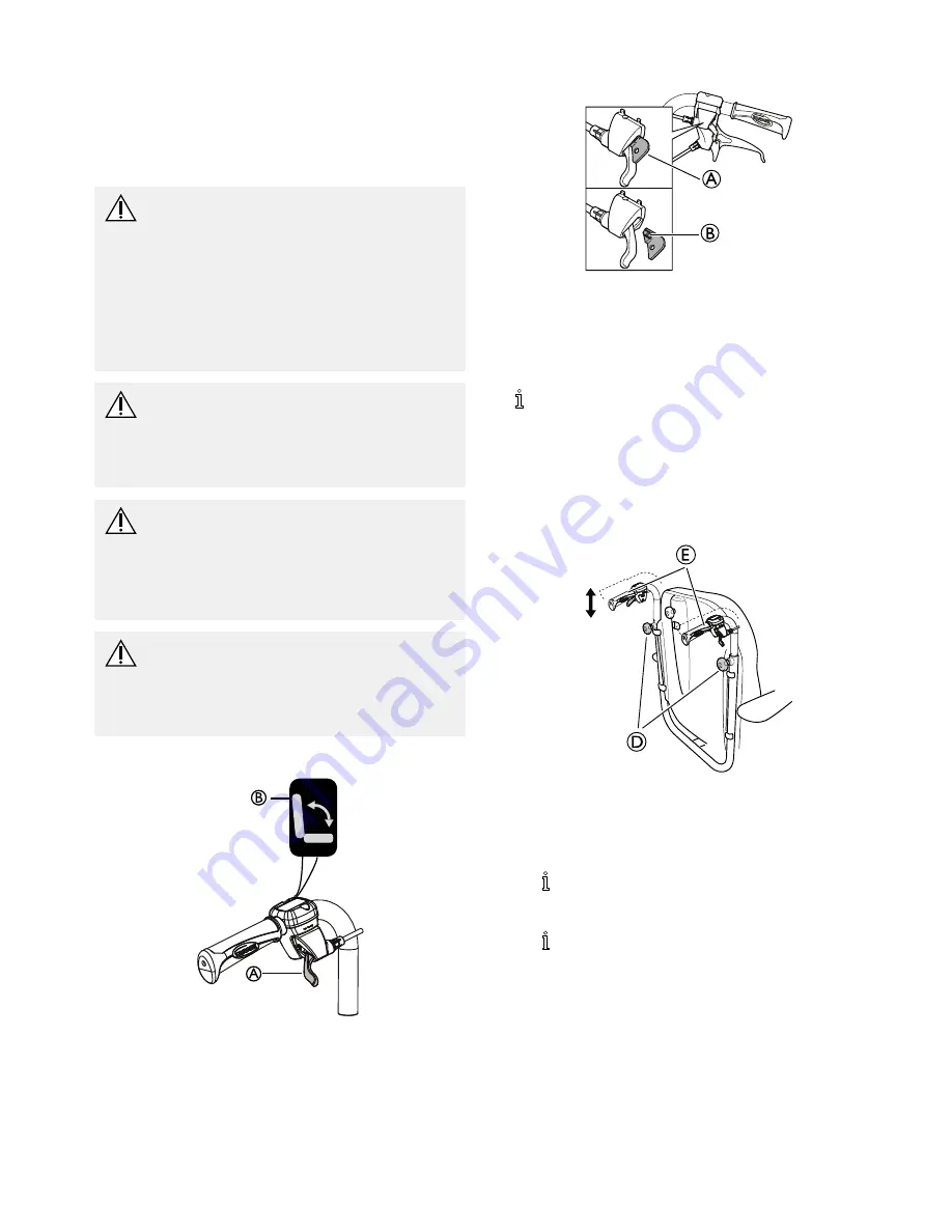
Use the
yellow
lever
A
marked with the
yellow symbol
B
on the
left
hand side to angle the backrest.
2.
Press upwards while you angle the backrest to the
desired position.
3.
Release the lever.
4.2.4 Tilting seat and backrest
WARNING!
Risk of fatal injury
Increased blood pressure against the upper part
of the body.
– All combinations of settings (like opened knee
angle + full tilt and recline) where the lower
extremity's are positioned higher than the heart,
have to be evaluated from a medical point of
view. The position can be contra indicated for
users who are sensitive for increased blood
pressure in the upper part of the body.
WARNING!
Risk of choking/breathing problems
The user might choke from eating or drinking
when seated in a tilted/reclined position
– The user must be seated in a raised position
before eating or drinking
WARNING!
Risk of injury
User may slide out of the wheelchair in a
tilted/reclined position
– Never leave the user at a flat of negative tilt
angle without supervision. Use the pelvic belt
for positioning.
CAUTION!
Risk of trapping fingers
– Be careful when adjusting the angle of the
backrest so that the assistant or user do not
trap fingers between the backrest and the
armrest.
Carer-operated tilt adjustment
B
A
1.
Use the
green
lever
A
with the
green symbol
B
on the
right
hand side to tilt the seat unit (seat and backrest).
2.
Press upwards while you tilt the seat unit to the desired
position.
3.
Release the lever.
Locking the tilt and/or backrest angle adjustment
A
B
The locking device
A
allows you to set the tilting of the seat
unit and/or the angling of the backrest to a fixed position.
1.
Tilt and/or angle the seat and backrest to the desired
position.
2.
Insert the locking device
A
.
The position is now set and cannot be changed.
To remove the locking device, press on the plastic peg
B
with a small object and pull outwards.
4.3 Adjusting the push handles
4.3.1 Backrest plate
E
D
1.
Loosen the hand wheels
D
. Adjust the push handles
to one of the four positions, then retighten the handle
wheels (B). After adjusting the push handles, always
make sure that the handle wheels are properly retighten.
2.
Adjust the push handles to the desired position.
There are four possible height positions, max
height adjustability is 90 mm.
3.
Retighten the hand wheels
D
.
Make sure that the hand wheels are properly
tightened.
4.
Adjust the height of the push handles (90 mm) by
loosening the handle wheels (B). Adjust the push handles
to one of the four positions, then retighten the handle
wheels (B). After adjusting the push handles, always
make sure that the handle wheels are properly retighten.
1439960-D
11


