background image

16

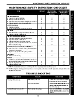
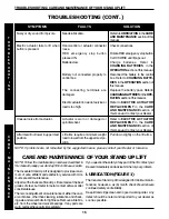
SYMPTOMS

FAULTS

SOLUTION

Needs lubrication.

Hand-control or actuator connector
loose.

RED emergency stop button
pressed IN.

Batteries low.

Battery not connected properly to
control box.

The connecting terminals are
damaged.

Electric actuator in need of service or
load is too high.

Actuator is worn or damaged or
spindle is bent.

Lift arms require a minimum weight
load to lower from the uppermost po-
sition.

Noisy or dry sound from pivots.

Electric actuator fails to lift when
button is pressed.

Unusual noise from actuator.

Lift arms will not lower in uppermost
position.

TROUBLESHOOTING (CONT.)

T

R

O

U
B

L

E
S

H

O
O

T

I

N

G

TROUBLESHOOTING / CARE AND MAINTENANCE OF YOUR STAND UP LIFT

NOTE: If problems are not remedied by the suggested means, please contact your Dealer or Invacare.

Refer to LUBRICATION in the CARE
AND MAINTENANCE 
 section of this
manual.

Check connections.

Rotate RED emergency stop button
CLOCKWISE until it pops out.

Charge batteries. Refer to
CHARGING BATTERIES  in the
OPERATION section of this manual.

Reconnect the battery to the control
box. Refer to CHARGING BATTE-
RIES  
in the OPERATION section of
this manual.

Replace the battery pack. Refer to
CHARGING BATTERIES  in the OPE-
RATION 
section of this manual.

Refer to ELECTRIC ACTUATOR
REPLACEMENT  
in the CARE
AND MAINTENANCE 
section of
this manual. Contact your Dealer.

Refer to ELECTRIC ACTUATOR
REPLACEMENT  
in the CARE
AND MAINTENANCE 
section of
this manual. Contact your Dealer.

Pull down slightly on the lift arms.

CARE AND MAINTENANCE OF YOUR STAND UP LIFT

C

A

R

E

-

M

A

I

N

T
E

N

A

N
C

E

NOTE: Follow the maintenance procedures described in
this manual to keep your stand up lift in continuous service.

The Invacare Stand Up Lift is designed to provide a maxi-
mum of safe, efficient and satisfactory service with mini-
mum care and maintenance.

All parts of the Invacare Stand Up Lift are made of the best
grades of steel, but metal to metal contact will wear after
considerable use.

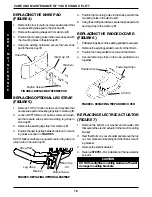
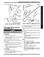
There is no adjustment or maintenance of either the cast-
ers or brakes, other than cleaning, lubrication and check-
ing axle and swivel bolts for tightness. Remove all debris,
etc. from the wheel and swivel bearings. If any parts are
worn, replace these parts immediately.

If you question the safety of any part of the lift, contact your
Dealer immediately and advise him/her of your problem.

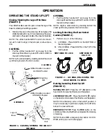
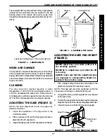
LUBRICATION (FIGURE 1)

The Invacare Stand Up Lift is designed for minimum main-
tenance; however, a six (6) month check should ensure
continued safety and reliability.

Keep lift and slings clean and in good working order.  Any
defect should be noted and reported to your dealer as
soon as possible.

Summary of Contents for RPS350-1

Page 1: ...ONCTIONNEMENT MANUAL DE INSTRUCCIONES Y MANTENIMIENTO DEALER THIS MANUAL MUST BE GIVENTOTHE USER OF THE PATIENT LIFT USER BEFORE USINGTHIS PATIENT LIFT READTHIS MANUALAND SAVE FOR FUTURE REFERENCE STAND UP LIFT MODEL RPS350 1 LÈVE PATIENT MODÈLE RPS350 1 LEVANTADOR MODELO RPS350 1 ...

Page 2: ...DEALER OR TECHNICAL PERSONNEL IF APPLICABLE BEFORE ATTEMPTING TO USE THIS EQUIPMENT OTHERWISE INJURY OR DAMAGE MAY RESULT RADIO FREQUENCY INTERFERENCE Most electronic equipment is influenced by Radio Frequency Interference RFI CAU TION should be exercised with regard to the use of portable communication equip ment in the area around such equipment If RFI causes erratic behavior PUSH the Red Emerge...

Page 3: ...11 TRANSFERRING TO 12 TRANSFERRING THE PATIENT TO A WHEELCHAIR 12 TRANSFERRING THE PATIENT TO A BED 13 TRANSFERRING THE PATIENT TO A COMMODE 14 MAINTENANCE SAFETY INSPECTION CHECKLIST 15 TROUBLESHOOTING 15 CARE AND MAINTENANCE OF YOUR STAND UP LIFT 16 LUBRICATION 16 WEARANDDAMAGE 17 CLEANING 17 ADJUSTING THE BASE 17 ADJUSTING THE KNEE PAD HEIGHT 17 REPLACING THE KNEE PAD 18 REPLACING OPTIONAL LEG ...

Page 4: ...octor nurseormedicalassistantforthecomfortandsafetyoftheindividualbeinglifted Before positioning the legs of the stand up lift around the patient make sure the patient s feet are out of the way of the footplate otherwise injury can occur Invacare recommends locking the rear swivel casters ONLY when positioning or removing the sling standing or transport from around the patient Invacare does NOT re...

Page 5: ...the factory and if service is required the motor unit MUST BE re turned to the factory for repair DO NOT attempt to open the motor or obtain local service as this will VOID the warranty and may result in damage and a costly repair Consult your Dealer or Invacare for further information Regular maintenance of Stand Up Lift and accessories is necessary to assure proper operation GroundingInstruction...

Page 6: ...ches Length 13 0 inches 36 0 inches FIGURE1 ATTACHINGMASTTOBASE 2 Removethehexbolt nutandwasher thatarelocated in the U shape cut out of the base 3 Positionthemastinanuprightpositionandplacethe mastontotheU shapedcut outofthebase 4 Insert hex bolt with washers through the base and mast Securewithnut WARNING Themastmayberemovedfromthebaseforstor age or transporting Each time mast is removed andretu...

Page 7: ...up lift and grasp the shifter handle with one 1 hand and place the oppo sitehandonthepushhandleofthemastforbalance NOTE The shifter handle MUST lock into its mount ing slot to lock the legs in the full open or closed posi tion CLOSING 1 Pull the shifter handle OUT and away from the stand up lift and then to your LEFT until it LOCKS in the notch of the bracket NOTE Left is determined by standing be...

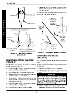
Page 8: ... 5 NOTE Invacare recommends the battery be recharged daily NOTE Anaudiblealarmwillsound hornwillbeep when batteryislow 1 Lift UP on the handle on the top of the battery 2 Lift the battery UP and OUT away from the control box WARNING Make sure there is an audible click when mounting battery on the battery charger to confirm proper mounting Otherwise injury or damage may occur Refer to FIG URE 5 for...

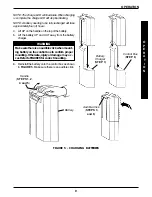
Page 9: ...way from the battery charger WARNING Makesurethereisanaudibleclickwhenmount ing battery on the control box to confirm proper mounting Otherwise injuryordamagemayoc cur Refer to FIGURE 5 for correct mounting 6 Reinstall the battery onto the control box as shown in FIGURE 5 Make sure there is an audible click FIGURE 5 CHARGING BATTERIES O P E R A T I O N OPERATION Battery Handle STEPS 1 2 4 and 5 Ba...

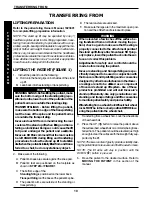
Page 10: ...NT in this section of the manual LIFTING PREPARATION Refer to the patient sling Owner s Manual 1023891 for complete lifting preparation information NOTE The stand up lift may be operated by one 1 healthcare professional for ALL lifting preparation trans ferring from and transferring to procedures with a coop erative weight bearingindividualabletosupportthema jority of his her own weight However si...

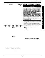
Page 11: ...ift DO NOT roll stand up lift over objects such as carpet raised carpet bindings doorframes oranyunevensurfacesorobstacles that would create an imbalance of the stand up lift and could cause the stand up lift to tip over UsepushhandleonthemastatALLtimestopush or pull the stand up lift 1 Using the push handle move the stand up lift away fromthesurface 2 SLOWLY movethepatienttothedesiredsurface 3 Lo...

Page 12: ...r wheel locks MUST be in the locked position BEFORE lowering the patient into the wheelchair 2 Lock the rear wheels of the wheelchair 3 Position the patient over the wheelchair 4 Press the DOWN ê button and lower the patient into the wheelchair WARNING Invacare recommends locking the rear swivel casters ONLY when positioning or removing the sling standing or transport from around the pa tient 5 Lo...

Page 13: ... supported by the lift 2 Press the DOWN ê button and lower the pa tient onto the bed WARNING Invacare recommends locking the rear swivel casters ONLY when positioning or removing the sling standing or transport from around the patient 3 Lock the rear swivel casters Refer to LOCKING UNLOCKING THE REAR SWIVEL CASTERS in the OPERATION section of this manual 4 Unhook the standing or transport sling fr...

Page 14: ...port sling from the bottom attachment points on the stand up lift Lift up on the patient s legs and remove the thigh supports from underneath the patient Ifdesired unhookthetransportslingfromthe top attachment points on the stand up lift NOTE Thepatientcanremainintheupperportionof the transport sling while using the commode 5 If equipped unfasten the leg strap from around the patient s legs 6 Inst...

Page 15: ...afety l Inspectslingmaterialforwear l Inspectstrapsforwear MAINTENANCE SAFETY INSPECTION CHECKLIST INITIALLY ITEM INSTITUTIONAL INSPECT ADJUST MONTHLY IN HOME INSPECT EVERY SIX 6 MONTHS X X X X X X X X X X X X X X X X X X X X X X X X X X X X X X X X X X X X X X X X X X X X X X X X X X X X X X I N S P E C T I O N C H E C K L I S T MAINTENANCE SAFETY INSPECTION CHECKLIST NOTE For individual home use...

Page 16: ...theOPE RATIONsectionofthismanual Refer to ELECTRIC ACTUATOR REPLACEMENT in the CARE AND MAINTENANCE section of this manual Contact your Dealer Refer to ELECTRIC ACTUATOR REPLACEMENT in the CARE AND MAINTENANCE section of this manual Contact your Dealer Pull down slightly on the lift arms CARE AND MAINTENANCE OF YOUR STAND UP LIFT C A R E M A I N T E N A N C E NOTE Follow the maintenance procedures...

Page 17: ...herthan 1 Check the squareness of the legs when in the CLOSED position 2 Place a square on the inside of the legs and base to determine the 90o alignment 3 Adjustthelinkagerodsuntil90o alignmentisachieved C A R E M A I N T E N A N C E CARE AND MAINTENANCE OF YOUR STAND UP LIFT FIGURE 1 LUBRICATION Lubricate the Bearings in the Caster Swivels ADJUSTING THE KNEE PAD HEIGHT FIGURE 3 FIGURE 3 ADJUSTIN...

Page 18: ...ver Lift Arm Fastening Strips REPLACING OPTIONAL LEG STRAP FIGURE 5 1 Remove TOP 2 button screws and washers that securekneepadandexistinglegstraptostanduplift 2 Loosen BOTTOM two 2 button screws and wash ers that secure knee pad and existing leg strap to stand up lift 3 Removetheexistinglegstrapfromstanduplift 4 Positionthenewlegstrapbetweenthefour 4 mount ing holes as shown in FIGURE 5 NOTE Make...

Page 19: ...OTE Thefrontcasterassemblyconsistsoftwo 2 cast ersandawasherinbetween NOTE The washer will fall out from between the two 2 casters NOTE Existing washer will be reused Examine and re placeifworn 3 Positionnew existingwasherbetweenthetwo 2 new casters 4 Line up the mounting holes in the new front caster assembly and the fork 5 Install the bolt through the fork and new front caster assembly and tight...

Page 20: ...ot return prod ucts to our factory without our prior consent C O D shipments will be refused please prepay shipping charges LIMITATIONS AND EXCLUSIONS THE FOREGOING WARRANTY SHALL NOT APPLY TO SERIAL NUMBERED PRODUCTS IF THE SERIAL NUMBER HAS BEEN REMOVED OR DEFACED PROD UCTS SUBJECTED TO NEGLIGENCE ACCIDENT IMPROPER OPERATION MAINTENANCE OR STORAGE PRODUCTS MODIFIED WITHOUT INVACARE S EXPRESS WRI...

Page 21: ...acareWay 5970 Chedworth Way Yes You Can and Invacare are registered trademarks of Elyria Ohio USA Mississauga Ontario InvacareCorporation 44036 2125 L5R3T9 Canada 2000 Invacare Corporation 800 333 6900 905 890 8838 Form No 98 137 Part No 1078984 Rev D 2 6 00 ...

Reviews: