


TRANSFERRING THE PATIENT
Stand Up Lift Model RPS350-2
26
Part No. 1145811
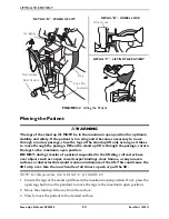
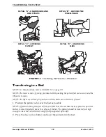
Transferring to a Commode
NOTE:
For
this
procedure,
refer
to
FIGURE 5.1.
WARNING
Invacare recommends locking the rear
swivel casters only when positioning or
removing the sling from around the
patient.
1. Lift
the
patient
from
the
bed.
Refer
to
Lifting
the
Patient
on
page 21.
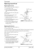
2. Press
the
boom
up
button
to
elevate
the
patient
high
enough
to
clear
the
arms
of
the
commode
chair.
Their
weight
will
be
supported
by
the
stand
up
lift.
Refer
to
Detail
“A”.
3. Guide
the
patient
onto
the
commode
chair.
This
may
require
two
assistants.
4. Press
the
down
arrow
button
to
lower
the
patient
onto
the
commode
chair.
5. Lock
the
rear
swivel
casters
on
the
stand
up
lift.
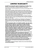
6. Perform
one
of
the
following
(refer
to
Detail
“B”):
• Standing
Sling
‐
unhook
the
standing
sling
from
the
attachment
points
on
the
stand
up
lift.
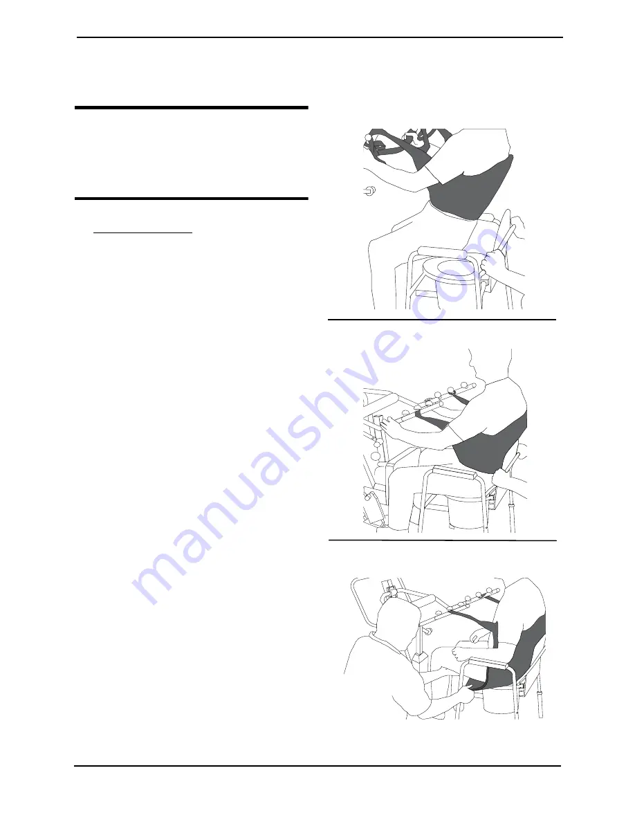
• Transport
Sling
‐
i. Unhook
the
transport
sling
from
the
bottom
attachment
points
on
the
stand
up
lift.
ii. Lift
up
on
the
patient’s
legs
and
remove
the
thigh
supports
from
underneath
the
patient.
iii. If
desired,
unhook
the
transport
sling
from
the
top
attachment
points
on
the
stand
up
lift.
NOTE:
The
patient
can
remain
in
the
upper
portion
of
the
transport
sling
while
using
the
commode.
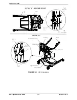
FIGURE 5.1
Transferring to a Commode
DETAIL “A” - POSITIONING PATIENT
DETAIL “B” - UNHOOKING SLING
DETAIL “C” - UNHOOKING SLING AND
STRAPS


