Invacare® SB® 755
4.
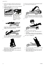
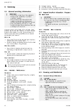
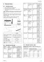
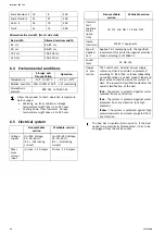
Insert the bolt
B
with washer
C
underneath the
mattress support frame and firmly tighten with a 6
mm Allen key on both brackets of the side rail.
5.
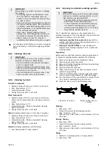
Repeat the procedure at the head end on the other
side of the bed or at the foot end on the same side
of the bed, depending on the side rail version used,
desired configuration and availability of additional side
rails.
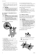
Dismount
1.
Untighten the bolts and remove on both side rail
brackets.
2.
Lift the side rail of the mattress support side tube.
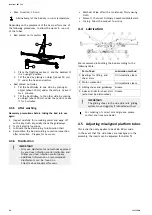
3.4 Wooden side panel
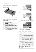
B
A
C
1.
Use the four screws and fasten each attachment
A
in the pre-drilled holes on the panels backside
B
(rounded corners up).
2.
Hang the attachments
A
on the bed frame
C
and
press it down firmly. Make sure it is pressed all the
way down.
3.5 Mattress support
CAUTION!
Handling of heavy parts
The lower part and upper part of the mattress
support can exceed the weight of 25 kg,
depending on configuration and bed size. See
weights table in chapter technical data.
– To reduce the weight below 25 kg per part,
dismount the motor from the upper part and
one or both motors from the lower part of
the mattress support.
3.5.1 Markings on washable bed
The upper half of the mattress support (head
section) is marked by a red dot and the lower half
of the mattress support (foot section) is marked
by a green dot.
3.5.2 Assembly of mattress support
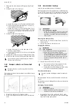
1.
Lock the brakes.
2.
Connect the plug to the mains socket.
3.
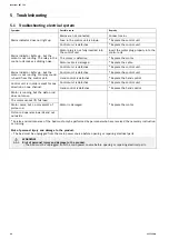
a. Take the hand control.
b. Tilt the lower part of the bed in over the shear arms
(while it is leaning on the bed end attachments).
c. Hold it and use the hand control to lower the bed
until the snap locks are fitted on the shear arms
pivots.
4.
Push the section slightly towards the middle until the
snap locks are activated with a clicking sound. Let it
lean as shown in the image.
Make sure the snap locks are properly engaged
before proceeding. If not, turn the red buttons
anti-clockwise to lock.
5.
Move over to the upper part of the mattress support.
10
1577126-H


