background image

Invacare® SB® 755

Scala Medium 2

20

8

200

Scala Decubi 2

29

21

200

Verso ll

18

10

200

Torill

16

12

200

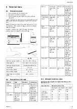
Allowed mattress width (for all side rails)

Bed width

Allowed mattress width

85 cm

83–85 cm

90 cm

88–90 cm

105 cm

103–105 cm

120 cm

118–120 cm

6.4 Environmental conditions

Storage and

Transportation

Operation

Temperature

-10°C to +50°C

+5°C to +40°C

Relative humidity

20% to 90% at 30°C - not condensing

Atmospheric
pressure

800 hPa to 1060 hPa

Allow the product to reach operation temperature
before usage:

Warming up from minimum storage
temperature might take up to 24 hours.

Cooling down from maximum storage
temperature might take up to 24 hours.

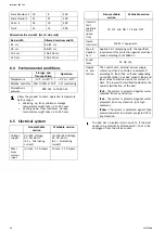
6.5 Electrical system

Non-washable

version

Washable version

Voltage
supply

Uin 230 Voltage,
AC, 50–60 Hz
(AC = Alternating
current)

Uin 100–240 Voltage,
AC, 50–60 Hz
(AC = Alternating
current)

Maxi-
mum
current
input

Iin max. 1,5 Ampere

Iin max. 2.5 Ampere

Non-washable

version

Washable version

Intermit-
tent
(periodic
motor
opera-
tion)

10 % 2 min ON / 18 min OFF

Insula-
tion class

CLASS II equipment

Type B
Applied
Part

Applied Part complying with the specified
requirements for protection against electrical
shock according to IEC60601-1.

Sound
level

55 dB (A)

Degree
of pro-
tection

The control unit, external power supply,
motors and hand controls are protected
according to IPx4, IPx6 or IPx6w (depending
on configuration). See bed product label and
label on each electric device for correct IP
class. The lowest IP-classification decides the
overall classification of the bed.

IPx4

- The system is protected against water

splashed from any direction.

IPx6

- The system is protected against water

projected from any direction (not high
pressure).

IPx6w

- The system is protected against high

pressurized water and steam projected from
any direction.

The bed has no isolator (main switch). If the bed
needs to be electrically disconnected, it has to be
unplugged from the mains socket.

24

1577126-H

Summary of Contents for SB 755

Page 1: ...Invacare SB 755 en Bed Service Manual DEALER Keep this manual The procedures in this manual MUST be performed by a qualified technician ...

Page 2: ...cation duplication or modification in whole or in part is prohibited without prior written permission from Invacare Trademarks are identified by and All trademarks are owned by or licensed to Invacare Corporation or its subsidiaries unless otherwise noted ...

Page 3: ...arms 13 3 6 2 Disassembly of shear arms 13 3 7 Wiring 13 3 8 Storage of disassembled bed on base frame 14 3 9 Mattress retainers 14 3 10 Limitation cross bar 15 3 11 Mattress support extension 15 3 12 Bumper wheels on Emma bed ends 16 3 13 Accumulator backup 16 4 Servicing 18 4 1 General servicing information 18 4 1 1 Checklist Maintenance 18 4 2 Inspection after relocation Prepare for new user 18...

Page 4: ...e user manual For more information about the product for example product safety notices and product recalls contact your Invacare representative See addresses at the end of this document 1 2 Symbols in this document Symbols and signal words are used in this document and apply to hazards or unsafe practices which could result in personal injury or property damage See the information below for defin...

Page 5: ...o big Follow the minimum width and length of mattresses in combination with a side rail as stated in the mattress table in chapter 6 Technical Data page 23 Be aware that using very thick or soft mattresses low density or a combination of these increases the risk A WARNING Risk of falling The user can fall over the edge and get seriously injured if the vertical distance A between the top of the mat...

Page 6: ...otal weight of the product with the maximum safe working load applied Temperature limit Humidity limitation Atmospheric pressure limitation Transport and storage conditions Operation conditions Label on 3 4 length side rails Indicates the maximum space between side rail and the head end of the bed Labels on Torill side rails 3 cm 6 cm A A A A Indicates the allowed mounting positions and spaces bet...

Page 7: ...t has reached a temperature of 10 40 C The assembly descriptions apply to all versions of the bed if nothing else is stated All references to left and right are based on a person lying on his back in the bed with his head towards the head end 3 1 1 Main parts of bed Parts of standard bed A Backrest I Mattress support lower half B Seat section J Backrest motor C Leg section motor K Base Frame D Thi...

Page 8: ...efully After each assembly check that all fittings are properly tightened and that the side rail has the correct function Removable 3 4 length side rails WARNING Risk of entrapment There s a risk of entrapment or suffocation between mattress support side rail and bed end When using removable side rails always make sure that the distance between the bed end and the side rail s handle upper edge is ...

Page 9: ...a screwdriver 3 Lower all three bars until they are out of the guideways 4 Repeat steps 2 to 3 to dismount the other end of the side rail 3 3 5 Installing the Torill side rail WARNING Risk of entrapment suffocation There s a risk of entrapment or suffocation between side rail and bed end Never install the short and the long version of the side rail on the same bed Always make sure that the left an...

Page 10: ...e weight of 25 kg depending on configuration and bed size See weights table in chapter technical data To reduce the weight below 25 kg per part dismount the motor from the upper part and one or both motors from the lower part of the mattress support 3 5 1 Markings on washable bed The upper half of the mattress support head section is marked by a red dot and the lower half of the mattress support f...

Page 11: ...mattress support 11 Connect all plugs from the section motors in the control box 12 Attach the locking cam over the plugs IMPORTANT After assembly of the mattress support check that all plugs motors and hand controls are correctly connected to the control unit according to the printed symbols that both sections of the mattress support are completely pushed together and the seat section completely ...

Page 12: ...to an upright position on the bed end attachments and fold out the backrest until it is in balance and let it stand aside 10 Plug in the main power plug in the control box and connect the main power 11 Move over to the lower part of the mattress support 12 Put the hand control within reach 13 Lift the thigh leg section up to reach the snap locks Pull out the red square locking buttons and turn the...

Page 13: ...ap lock is engaged 3 6 2 Disassembly of shear arms 1 Lock the brakes 2 Use the hand control to lower the shear arms completely down 3 Take hold of the small handle located next to the controls with one hand 4 Loosen the locking pin 5 Lift the shear arm to an upright position 6 Turn the shear arm and hold it towards the body before lifting 7 Lift the shear arms out of the base 3 7 Wiring IMPORTANT ...

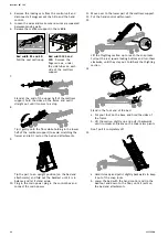
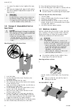
Page 14: ... and distance pin properly fastened 9 Fold down both transport hooks C for the accessories 10 Place the bed ends and side rails on the hooks 11 Place the mattress between the sections 12 Place the lifting pole in the tube D on the base frame Make sure all wires and the hand control are properly secured to avoid damage during transport Dismount the parts from the base frame 1 Lock the brakes 2 Remo...

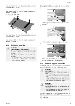
Page 15: ...n crossbar under the leg section 1 Lift the leg section of the mattress support to free the base 2 Fit the crossbar into place and tighten the screws 3 When properly installed the leg section of the mattress support leans on the crossbar 3 11 Mattress support extension For patients taller than two meters it is recommended to extend the bed with a mattress support extension WARNING Risk of injury T...

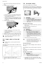
Page 16: ...s that the bed can be adjusted during a power failure or transport A B IMPORTANT Low accumulator capacity When the accumulator only has capacity left for one more lifting cycle the control box will make an audible sound when using the hand control Mounting the backup battery 1 Install the box on the bed s base frame next to the control unit B 2 Connect the cable to the control unit Charging the ba...

Page 17: ...ype or mechanically and electrically compatible accumulators 12V 1 2 Ah Accumulators in a set must have identical production codes Prior to insertion make sure that the accumulator set is correctly connected according to the drawing in the accumulator box and that none of the connections are loose 1577126 H 17 ...

Page 18: ...amaged q Cable insulation and actuator housings no cracks or damages q Damaged coating repaired q Line side rail straps not frayed or cracked q Accessories correctly assembled and correct function 4 2 Inspection after relocation Prepare for new user IMPORTANT When the bed has been relocated before given to a new user it has to be thoroughly inspected Inspection must be done by a trained profession...

Page 19: ... Textiles including upholstery and mattresses See attached label on each product 4 3 4 Cleaning in automatic washing systems IMPORTANT Only certain components of the product tolerate cleaning in automatic washing systems or with high pressure cleaning equipment The washability of the components must be determined by authorized personnel If the components cannot tolerate cleaning in automatic washi...

Page 20: ...relocation Prepare for new user 4 3 6 Disinfection IMPORTANT Only use disinfectants and methods approved by your local infection control institution and follow your local infection control policy Additional information on recommended disinfectants can be found on https vah online de en for users Method Wipe off with a moistened firmly wrung cloth Solvent chemical Ordinary household disinfectant Dr...

Page 21: ...sposal Be environmentally responsible and recycle the different materials and components of this product separately through your recycling facility at its end of life The disposal and recycling of used products and packaging must comply with the laws and regulations for waste handling in each country Contact your local waste management company for information 1577126 H 21 ...

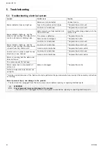
Page 22: ...is not running No relay sound is heard from the control unit Hand control is defective Replace the hand control Control unit is defective Replace the control unit Control unit is in order except for one direction on one channel Hand control is defective Replace the hand control Motor is running but the piston rod does not move The motor cannot lift full load Motor noise but no movement of piston r...

Page 23: ...length aluminium side rail with telescopic extension 206 226 cm x 40 cm Mounted on the bed end guideways Release buttons in the middle Britt V Full length wood side rail 205 cm x 40 cm Mounted on the bed end guideways Release buttons in the middle Scala Basic 2 Scala Basic Plus 2 3 4 length collapsible steel side rail 168 cm x 40 cm Mounted on the side tube Release button in the head section Scala...

Page 24: ...n max 1 5 Ampere Iin max 2 5 Ampere Non washable version Washable version Intermit tent periodic motor opera tion 10 2 min ON 18 min OFF Insula tion class CLASS II equipment Type B Applied Part Applied Part complying with the specified requirements for protection against electrical shock according to IEC60601 1 Sound level 55 dB A Degree of pro tection The control unit external power supply motors...

Page 25: ...Notes ...

Page 26: ...Notes ...

Page 27: ...Notes ...

Page 28: ... 353 1 810 7085 ireland invacare com www invacare ie United Kingdom Invacare Limited Pencoed Technology Park Pencoed Bridgend CF35 5AQ Tel 44 0 1656 776 222 Fax 44 0 1656 776 220 uk invacare com www invacare co uk Manufacturer Invacare Rea AB Växjövägen 303 SE 343 71 Diö Sweden 1577126 H 2018 10 30 1577126H Making Life s Experiences Possible ...

Reviews: