background image

8

Operation

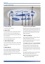
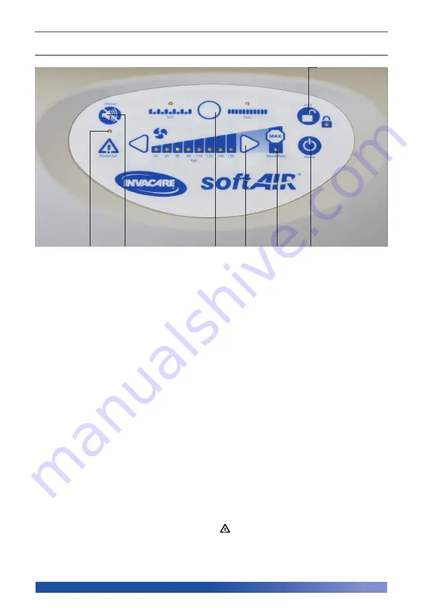
Control Unit Panel

A

 Power Button

Turns system power on and off.

B

 Alarm LED

The red light will flash and an audible alarm will sound 
to alert when the Control Unit or mattress pressure 
fails. The alarm has five different signals to indicate the 
cause of the failure.

The audible alarm also sounds when power is switched 
off. Press the Alarm Mute to silence.

C

 Alarm Mute Button

This button silences the audible alarm (on/ off). Audible 
alarm will resume after 20 minutes if cause of failure is 
not resolved

.

D

 Mode Button

Press to select either Alternation Mode (alternative 
cells cyclically inflating and deflating) or Static Mode 
(all cells fully inflated with no dynamic alternation). 
Static Mode will automatically revert back to Alternation 
Mode after 20 minutes.

E

 Pressure Arrow Buttons

Press the arrows to increase or decrease the pressure 
setting. Eight pressure settings are available from soft 
to hard (18mmHg to 60mmHg; 6mmHg per step). The 
green LEDs illuminate to indicate which of the eight 
settings is operational.

Max Firm Button

Press to facilitate rapid inflation to maximum pressure 
setting (60mmHg). After 30 minutes,  
the system automatically reverts back to the previous 
pressure setting for patient safety.

G

 Control Unit Lock / Unlock Button

Press for at least two seconds to lock the Control 
Unit settings. A beep sounds and the amber LED 
illuminates to indicate system is locked. When locked, 
only the Alarm Mute and Lock / Unlock buttons remain 
operational.

Press again for at least two seconds to unlock. Again a 
beep sounds and the amber LED turns off. 

  The Control Unit will automatically unlock 

in the event of a power failure.

G

A

B

C

D

E

F

<

<

Summary of Contents for SoftAir EXCELLENCE

Page 1: ...SoftAirEXCELLENCE250mmAlternatingMattressSystem User Manual...

Page 2: ...mportant to read this manual and understand the operating instructions and safety precautions Failure to do so could result in patient injury and or damage to the product If you have any questions ple...

Page 3: ...tem Installation 7 Control UnitActivation 7 OPERATION 8 Control Unit Panel 8 Mattress Function 9 Alarm Functions 10 Removal Transport Function 11 TROUBLESHOOTING 12 CLEANING 14 MAINTENANCE 16 TECHNICA...

Page 4: ...se the power cord supplied with the system Exposure of the electronic Control Unit to any liquid while it is plugged in could result in a severe electrical hazard Always use fuses of the same rating a...

Page 5: ...trolunitarefourmaleairconnectors forconnectingthehandle Therapidreleasehandleincludesacapwhichcanbe insertedintothehandleduringtransportation Whenin transportationmode testshaveproventhatthesystem wil...

Page 6: ...e that may have occurred during transportation Any damaged or missing parts must be reported to your local Invacare Ltd sales office immediately Please refer to the back page for contact details SoftA...

Page 7: ...ide rails as straps will tear a Position the Control Unit by placing the hooks over the foot board of the bed or side rails b Connect the handle to the Control Unit Ensure the air hose does not kink b...

Page 8: ...back toAlternation Mode after 20 minutes E Pressure Arrow Buttons Press the arrows to increase or decrease the pressure setting Eight pressure settings are available from soft to hard 18mmHg to 60mmHg...

Page 9: ...wered 5 Repeat the Bottoming Out test after pressure has been lowered In the event of a system malfunction the alarm will activate and pressure LEDs will flash Establishing Pressure inclined position...

Page 10: ...s and corresponding Pressure Setting LED displays are illustrated below Operation Display Alarm Signal Initial Failure Mattress has failed to reach minimum operational pressure within 50 minutes Low P...

Page 11: ...nce transportation is complete Regularly perform a Bottoming Out test to ensure the patient is appropriately supported as air pressure is released from all internal static cells as well as alternating...

Page 12: ...oses Check the CPR tag is attached and both sealing connectors are firmly secure 3 Check all air hoses along the inside of the mattress each should be firmly connected Check each air cell is securely...

Page 13: ...t the air hoses to reduce pressure reconnect when pressure has decreased 3 Check for twists in the air hoses between the mattress and Control Unit 4 Switch on Power Patient is sinking or bottoming out...

Page 14: ...n heat dry cycle If there are no visible signs of body fluids and or substances on the top cover the top cover should be sanitised 1 Apply an intermediate level disinfectant or a solution of Sodium Hy...

Page 15: ...to prevent scratches 4 Carefully remove the air filter cover Remove and discard the filter and fit with a new filter there may be a small locking screw use a small Phillips Head screwdriver to remove...

Page 16: ...2000mm Width 830mm 880mm Height 250mm including side formers Weight 9 5kg 10 8kg Control Unit Dimensions Length 290mm Width 170mm Height 270mm Weight 3 2kg Cell Material 0 15mm TPU film laminated on 2...

Page 17: ...prior to return Returns should include information describing the problem and or requested repair and be sent to your local Invacare Ltd sales office by prepaid transportation Invacare Ltd will return...

Page 18: ...ark Tel 45 58 85 27 22 Fax 45 58 85 43 86 Invacare Norway Invacare AS Grensesvingen 9 Postboks 6230 Etterstad N 0603 Oslo Norway Tel 47 22 57 95 00 Fax 47 22 57 95 01 Invacare Sweden Invacare AB Fager...

Reviews: