12
60129676-A
Invacare
®
Softform Active
®
2 Rx
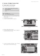
5. Unplug the black and green wires
D
from the
microswitch.
6. Loosen and remove the four screws
fixing the
PCB to the front housing.
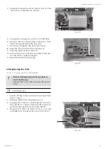
7. Unplug the yellow motor wire
E
from the PCB.
8. Slide the PCB from under the microswitch and
remove it from the housing. Unplug the five
remaining wires from the PCB. Discard the
non-functioning PCB.
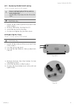
9. Connect the five cables to the new PCB, in their
original position: green and black power switch
wire
F
, green and black micro switch wire
G
, 6-pin
user interface wire
H
, red compressor wires
I
and red and black fuse holder wire
J
.
10. Install the new PCB on the front housing, ensuring
the yellow motor wire
E
goes under it.
11. Install the provided screws and tighten them.
12. Plug the yellow motor wire to its original position.
13. Plug the microswitch wires
(see step 5).
14. Place the longer silicon tube (the one with the
T-valve), counterclockwise, around the motor.
E
Fig. 4-18
F G H
I
J
Fig. 4-19
Fig. 4-20
D
D
Fig. 4-17


