background image

Spartan and Sprint Rollators

2

Part No 1076166


INSTALLATION WARNINGS

Always test to see that the rollator is properly and securely locked when in 

the open position before using.
The rollator height can be adjusted only where the push handle is textured 

(FIGURE 3).
After installation and before use, ensure that all attaching hardware is 

securely tightened.

Opening/Folding Rollator

NOTE: Refer to Safety Summary on page 1 of this instruction sheet. 

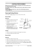
Model 65400

Opening

1. Remove the rollator from the carton.

2. Pivot left and right side frames 

outward.

3. Push down on the side of the center 

tab so that the lock support 
mechanism is straight.

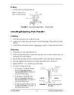
4. Install the push handles into the 

side frame. Refer to 
Installing/Adjusting Push Handles 
on page 3 in this instruction sheet.

FIGURE 1   

Opening/Folding Rollator - 

Model 65400

Folding

1. Pull up on center tab to release the lock support mechanism.

2. Pivot left and right side frames inward.

Model 65420

Opening

1. Remove the rollator from the carton.

2. Remove the shipping tube that extends between the two (2) rear wheels.

3. Hold cutout in seat and push down on seat until an audible “click” is heard.

4. Install the push handles into the side frame. Refer to Installing/Adjusting Push 

Handles on page 3 in this instruction sheet.

Right Side 

Frame

Lock Support 

Mechanism

Center Tab

Left Side 

Frame

Summary of Contents for Spartan 65400

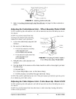
Page 1: ...cure and that casters and moving objects are in good working order before using this or any mobility aid All wheels MUST be in contact with the floor at all times during use On Model 65420 the brakes...

Page 2: ...n the side of the center tab so that the lock support mechanism is straight 4 Install the push handles into the side frame Refer to Installing Adjusting Push Handles on page 3 in this instruction shee...

Page 3: ...grip is at wrist height 3 Ensure that the push handle is adjusted ONLY where the tubing is textured 4 Securely tighten push handle by turning adjustment lever clockwise 5 Repeat STEPS 1 3 for remainin...

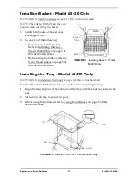
Page 4: ...using the rollator refer to Using Hand Brakes on page 5 of this instruction sheet FIGURE 4 Installing Basket Model 65420 Only Installing the Tray Model 65420 Only NOTE Refer to Installation Warnings o...

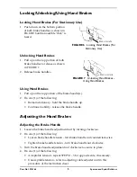
Page 5: ...on of the brake handle s 2 Do one 1 of the following Remain stationary hold the brake handle up Continue mobility release the brake handle Adjusting the Hand Brakes Adjusting the Brake Handle 1 Loosen...

Page 6: ...cable adjuster unit locknut FIGURE 9 Adjusting the Cable Adjuster Unit Wheel Assembly Model 65400 4 Test the brake If the tension of the brake handle is still too loose tight perform the following A R...

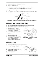
Page 7: ...ing up 3 Remove the four 4 screws washers and two 2 spacers that secure the seat to the frame 4 Remove the four 4 screws and two 2 brackets that secure the seat to the frame 5 Remove the existing seat...

Page 8: ...TIONS AND EXCLUSIONS The warranty shall not apply to problems arising from normal wear or failure to adhere to the enclosed instructions In addition the foregoing warranty shall not apply to serial nu...

Reviews: