background image

SECTION 6—SEAT - TDX SC ONLY

TDX® SC TDX® Spree

48

Part No 1149267

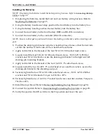
8. Remove


prop


rod


from


the


clip


located


on


the


Formula


CG


frame


and


engage


the


prop


rod


end


into


the


front


seat


post.

9. Gently


allow


weight


of


seat


assembly


to


be


supported


by


the


prop


rod.

NOTE:


Only


leave


the


seat


assembly


in


the


UP/OPEN


position


while


performing


any


necessary


procedures.


Always


lower


the


seat


assembly


to


the


DOWN/CLOSED


position


when


not


servicing


the


wheelchair.


Ensure


the


seat


is


locked


in


place


before


using.

Tilting the Seat Assembly Forward

1. Using


one


hand,


firmly


grasp


the


front


edge


of


the


seat


assembly


and


lift


until


seat


assembly


is


no


longer


supported


by


the


prop


rod.

2. Disengage


the


prop


rod


from


the


front


seat


post


and


secure


into


clip.

3. Using


both


hands,


slowly


tilt


the


seat


assembly


FORWARD


into


the


DOWN/CLOSED


position.


WARNING

Ensure the two mounting screws, washers and locknuts are securely tightened and 

the seat frame is locked in place before use - otherwise injury or damage may result.

4. Using


the


two


mounting


screws,


washers


and


locknuts,


secure


the


seat


frame


plate


to


the


two


front


seat


posts.

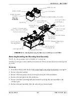
FIGURE 6.2   

 - Tilting the Seat Assembly - Wheelchairs without Latch Bar Only

Seat Frame Plate

Mounting Screw

Washer and Locknut

Front Seat Post

DOWN/CLOSED 

Position

UP/OPEN 

Position

NOTE:


Seating


system


not


shown.

Summary of Contents for TDX SC

Page 1: ...UST be given to the user of the wheelchair USER BEFORE using this wheelchair read this manual and save for future reference For more information regarding Invacare products parts and services please v...

Page 2: ...ler or technical personnel before attempting to use this equipment otherwise injury or damage may occur ACCESSORIES WARNING Invacare products are specifically designed and manufactured for use in conj...

Page 3: ...s 15 Batteries 15 Charging Batteries 16 Rain Test 16 Weight Training 17 Weight Limitation 17 SECTION 2 EMI INFORMATION 18 SECTION 3 SAFETY HANDLING OF WHEELCHAIRS 20 Stability and Balance 20 Coping wi...

Page 4: ...Programming Input 36 Service Indicator 36 Information Gauge Display 37 MPJ Joystick Switches and Indicators 37 Drive Select Toggle Switch 37 Speed Control 38 Joystick 38 Charger Programming Input 38...

Page 5: ...t 54 Wheelchairs with Elevating Seat 55 SECTION 12 BATTERIES 56 Warnings For Handling and Replacing Batteries 56 Using the Proper Batteries 57 Removing Installing the Batteries 57 Removing Installing...

Page 6: ...pliance Information 73 Specifications 74 Securing the Wheelchair to the Vehicle 74 Positioning the Wheelchair in the Vehicle 74 Securement Points 75 Securing the Wheelchair 75 Securing the Occupant 76...

Page 7: ...nd servicing of your product 3 Receiving updates with product information maintenance tips and industry news Register ONLINE at warranty invacare com Please have your model number and purchase date av...

Page 8: ...son with a weight of 125 to 165 lbs for Junior seat sizes or a 168 lb crash dummy which corresponds to a person with a weight of 165 to 300 lbs for Adult seat sizes TRBKTS includes four factory instal...

Page 9: ...ides the wheelchair with optimum traction and stability when driving forward over transitions and thresholds of up to 2 3 8 inches 60mm The following warnings apply specifically to the SureStep featur...

Page 10: ...nect to the POSITIVE BatteryTerminal s Post s The NEGATIVE BLACK Battery Cable MUST connect to the NEGATIVE BatteryTerminal s Post s DO NOT allow Battery Cable s to contact the opposite Battery Termin...

Page 11: ...LIES WITH ANSI RESNA WC 19 Refer to attached TRANSPORT READY OPTION Instruction card and wheelchair Owner s Manual before use Lower seat to lowest position ensure docking pins are fully engaged and po...

Page 12: ...IES WITH TWO U1 BATTERIES 178 lbs 225 lbs 183 230 MOTOR 2 Pole DRIVE AXLE Non adjustable DRIVE WHEELS TIRES 10 x 3 inch Foam Filled CASTERS 6 x 2 inch Semi pneumatic with Precision Sealed Bearings CAS...

Page 13: ...Invacare and are not recommended for use with Invacare products Transport ready packages are not retrofittable to existing models and are not field serviceable Wheelchairs should be examined during ma...

Page 14: ...ip over ALWAYS shift your weight in the direction you are turning DO NOT shift your weight in the opposite direction of the turn Shifting your weight in the opposite direction of the turn may cause th...

Page 15: ...e off position Wheelchairs with TRRO or TRBKTS Only Only use the transport brackets included with TRRO and TRBKTS for the purposes described in this manual Electrical Grounding Instructions DO NOT und...

Page 16: ...s for each charger supplied or purchased If charging instructions are not supplied consult a qualified technician for proper procedures Ensure the pins of the extension cord plug are the same number s...

Page 17: ...for any kind of weight training If occupant uses said wheelchair as a weight training apparatus INVACARE SHALL NOT BE LIABLE FOR BODILY INJURY AND THE WARRANTY IS VOID Weight Limitation Refer to Typic...

Page 18: ...tection from the more common sources of radiated EMI There are a number of sources of relatively intense electromagnetic fields in the everyday environment Some of these sources are obvious and easy t...

Page 19: ...ELEASE OR POWERED WHEELCHAIR MOVEMENT WHICH COULD RESULT IN SERIOUS INJURY 1 Do not operate hand held transceivers transmitters receivers such as citizens band CB radios or turn ON personal communicat...

Page 20: ...s in this manual are a starting point for the new wheelchair user and assistant with safety as the most important consideration for all Stability and Balance WARNING ALWAYS wear your seat positioning...

Page 21: ...yond the center of gravity DO NOT lean forward out of the wheelchair any further than the length of the armrests Make sure the casters are pointing in the forward position whenever you lean forward Th...

Page 22: ...as lifting supports as they may be inadvertently released resulting in possible injury to the user and or assistant s When learning a new assistance technique have an experienced assistant help you be...

Page 23: ...eelbase Reach back only as far as your arm will extend without changing your sitting position FIGURE 3 3 Reaching Bending Backward Pinch Points WARNING A pinch point exists between head tube cap and w...

Page 24: ...injury to the user or damage to the wheelchair The weight of the wheelchair without the user and without batteries is between 178 and 230 lbs Use proper lifting techniques lift with your legs to avoi...

Page 25: ...his will prevent broken screws damaged upholstery and the possibility of the wheelchair tipping forward NOTE For this procedure refer to FIGURE 3 5 NOTE Adequate mobility and upper body strength is re...

Page 26: ...ve drag or pull to one side Inspect all fasteners Inspect TRRO TRBKTS fasteners and hardware Ensure clothing guards are secure Ensure arms are secure but easy to release and adjustment levers engage p...

Page 27: ...casters are spun when free wheeling Wheels casters should come to a gradual stop Ensure that casters are free of debris Ensure arm pivot points are free of wear and looseness Ensure all caster wheel...

Page 28: ...casters have proper tension when wheels casters are spun when free wheeling Wheels casters should come to a gradual stop Ensure that casters are free of debris Inspect foam handgrips for damage If dam...

Page 29: ...ht will flash The number or type of flashes indicates the nature of the error If multiple errors are found only the first error encountered by the control module will be displayed Information Gauge Di...

Page 30: ...es on page 65 3 Left Motor Fault Contact Invacare Dealer for service 4 Right Motor Fault Contact Invacare Dealer for service 5 Left Park Brake Fault Contact Invacare Dealer for service 6 Right Park Br...

Page 31: ...The joystick or input device is sending a value outside of the reverse forward left or right limits Error codes E01 E02 E03 or E04 Replace joystick or input device NEUTRAL TESTING displays The joystic...

Page 32: ...ds Poor battery terminal connection Have terminals cleaned Power indicator off even after recharging Electrical malfunction Contact Dealer Invacare for Service DON T DO Don t perform any installation...

Page 33: ...llowing steps 2 Turning the power Off can be achieved by performing one of the following steps FIGURE 5 1 Turning the Power On Off Using the Joystick to Drive the Wheelchair NOTE For this procedure re...

Page 34: ...chair perform the following 1 Adjust speed control knob to the appropriate setting 2 Turn the power On Refer to Turning the Power On Off on page 33 3 Maneuver the joystick in the following manner FIGU...

Page 35: ...mmed Speedometer The speedometer is used to show the maximum speed The right most LED indicates current maximum speed setting The bottom left GREEN LED flashes to indicate that the joystick is in spee...

Page 36: ...are button to decrease increase the speed in smaller increments The smaller bars in the speedometer will light Joystick The joystick has proportional drive control meaning that the further the joystic...

Page 37: ...to FIGURE 5 4 on page 38 Drive Select Toggle Switch The drive select toggle switch is located on the left side below the LCD The drive select position is momentary meaning that it will return to the...

Page 38: ...ir to a stop simply release the joystick The wheelchair has automatic speed and direction compensation to minimize corrections Charger Programming Input The charger programming input is located at the...

Page 39: ...y and F Full As the battery becomes discharged the top most segments will progressively disappear until no segments appear between E and F At this level the user should charge the batteries as soon as...

Page 40: ...not be allowed to operate The status indicator shows an Attendant Icon if the attendant s override switch is active MODES The dotted box shows the area that contains the available modes in the cur ren...

Page 41: ...f the joystick on the left side The programmable mono port input offers the choice of three options Remote drive select Remote stop mode reset input Single actuator input The single switch functions o...

Page 42: ...n the joystick A mode switch is needed whenever any of the following operating modes are programmed Environmental Controls ECU 1 ECU 2 ECU 3 ECU 4 3 Speed Mode in Digital 3 Speed Slow Medium Full Latc...

Page 43: ...side of the armrest plate 4 Reposition the mounting bracket on the opposite armrest plate 5 Using the three hex mounting screws bushings and locknuts secure the mounting bracket to the three mounting...

Page 44: ...e ensuring the threaded plate of the mounting bracket is on the inside of the arm tube as shown in FIGURE 5 10 FIGURE 5 10 Repositioning Joystick Adjustable ASBA Seats 5 Using the three hex mounting s...

Page 45: ...stick connector with one hand and the controller connector on the wheelchair in the other and align them 2 Lightly push to engage the joystick connector and the controller connector FIGURE 5 11 Discon...

Page 46: ...Refer to Disconnecting Connecting the Joysticks on page 45 NOTE The latch bar will be located behind the front seat posts on wheelchairs with adjustable ASBA seats and in front of the front seat post...

Page 47: ...ery compartment The seat assembly tilts back and props into place to provide access to the batteries and the underside of the seat Tilting the Seat Assembly Back 1 Place the wheelchair in a well venti...

Page 48: ...asp the front edge of the seat assembly and lift until seat assembly is no longer supported by the prop rod 2 Disengage the prop rod from the front seat post and secure into clip 3 Using both hands sl...

Page 49: ...cedure refer to FIGURE 7 1 NOTE Motor lock disengagement engagement allows free wheeling or joystick controlled operation Free wheeling allows an assistant to maneuver the wheelchair without power NOT...

Page 50: ...d otherwise damage to the wheelchair may result NOTE Use the wheel locks whenever the clutches are disengaged and the wheelchair is being pushed Disengaging Engaging the Wheel locks NOTE For this proc...

Page 51: ...e footboard while operating the wheelchair If the user s feet are allowed to rest off the side of the footboard they may come in contact with the caster possibly resulting in injury Removing Installin...

Page 52: ...d underneath on the rear of the footplate 2 Adjust the mounting screw in or out to obtain the desired footboard angle 3 Thread the jam nut inward until it is flush with the footboard bracket 4 Securel...

Page 53: ...eadtube cover not shown from the caster headtube 3 To properly tighten caster journal system and guard against flutter perform the following check A Tip back the wheelchair to floor B Pivot both forks...

Page 54: ...on the wheels Flat spots will vanish with continued use of the wheelchair Removing Installing the Top Shroud Wheelchairs without Elevating Seat NOTE For this procedure refer to FIGURE 11 1 NOTE Revers...

Page 55: ...he seat Refer to the seating system owners manual 2 Remove the four thumb screws securing the rear half of the top shroud to the wheelchair fame 3 Pulling up remove the rear half of the top shroud 4 P...

Page 56: ...low any of your tools and or battery cables to contact both battery posts at the same time An electrical short may occur and serious personal injury or damage may occur The POSITIVE battery cable MUST...

Page 57: ...tteries with terminal configuration as shown below MUST be used Batteries that have the reverse terminal configuration MUST NOT be used otherwise injury and damage may occur FIGURE 12 1 Using the Prop...

Page 58: ...lting the Seat Assembly Wheelchairs without Latch Bar Only on page 47 4 Remove the battery shroud Refer to Removing Installing the Top Shroud on page 54 5 Disconnect the rear battery from the controll...

Page 59: ...chair If there is no power left in the batteries Remove the seat frame from the wheelchair Refer to Removing Installing the Elevating Seat Assembly on page 63 3 Verify the joystick On Off switch is in...

Page 60: ...the front battery into the battery box 3 Using the battery handle position the rear battery into the battery box 4 Connect the rear battery to the front battery RED and BLACK connectors 5 Connect the...

Page 61: ...joystick Refer to Disconnecting Connecting the Joysticks on page 45 4 Remove the top shroud Refer to Removing Installing the Top Shroud on page 54 5 Remove the four 5 16 18 X 2 00 socket head screws...

Page 62: ...notches in both sides of the wheelchair base frame 7 Apply loctite 242 to the threads of the four 5 16 18 X 2 00 socket head screws 8 Loosely install the four 5 16 18 X 2 00 socket head screws 330 X 6...

Page 63: ...t frame 4 Remove the seat pan from the seat frame 5 Remove the four mounting bolts and locknuts securing the seat assembly to the actuator post 6 Remove the seat assembly from the actuator post and se...

Page 64: ...at frame as shown 4 Using the two socket screws secure the seat pan to the seat frame 5 Install the seat cushion 6 Connect the joystick Refer to Disconnecting Connecting the Joysticks on page 45 FIGUR...

Page 65: ...ry terminals at the same time An electrical short may occur and serious personal injury or damage may occur NOTE For this procedure refer to FIGURE 12 6 on page 67 1 Remove the batteries Refer to Remo...

Page 66: ...be installed prior to use CAUTION When connecting the battery cables to the battery the battery cables MUST be connected to the battery terminals as shown in Detail A of FIGURE 12 6 depending on batte...

Page 67: ...cknuts U1 Battery POSITIVE Battery Terminal Cap DETAIL A DETAIL B NOTE Handles on batteries removed for clarity POSITIVE Battery Terminal NEGATIVE Battery Terminal Tie wraps U1 Battery U1 Batteries BL...

Page 68: ...RED LEDs are lit indicating batteries are running out of charge Recharge batteries as soon as possible FIGURE 12 7 SPJ SPJ w PSS and SPJ w ACC Joysticks MPJ Joystick NOTE For this procedure refer to F...

Page 69: ...e using recommended batteries should be approximately 5 to 9 hours of typical operation Extensive use on inclines may substantially reduce per charge mileage Description and Use of Battery Chargers Th...

Page 70: ...hours for normal charging Larger batteries greater than 55 ampere hours or severely discharged batteries may require up to sixteen hours to be properly charged and equalized NOTE It is advantageous t...

Page 71: ...s a form of acid and harmful or damaging burns may result Should the liquid touch your skin wash the area IMMEDIATELY and thoroughly with cool water In serious cases or if eye contact is made seek med...

Page 72: ...seating system ONLY This wheelchair MUST be in a forward facing position during travel in a motor vehicle This wheelchair is equipped and has been dynamically tested to rely on WHEELCHAIR ANCHORED pe...

Page 73: ...he U S Department of Transportation has not approved any tie down systems for transportation of a user while in a wheelchair in a moving vehicle of any type It is Invacare s position that users of whe...

Page 74: ...one of 16 inches is measured from the rearmost point on an occupant s head The frontal clear zone is measured from the frontmost point on an occupant s head and is 26 inches with pelvic and upper tors...

Page 75: ...en installed in accordance with the manufacturer s instructions and SAE J2249 NOTE A copy of SAE J2249 Wheelchair Tie down and Occupant Restraint Systems WTORS for use in Motor Vehicles can be obtaine...

Page 76: ...of the vehicle If necessary follow the instructions below to reverse the orientation of the pelvic belt to accommodate the vehicle anchored upper torso belt 1 Install the pelvic belt pin Detail A of F...

Page 77: ...1149267 77 TDX SC TDX Spree FIGURE 13 2 Wheelchair Anchored Belts Pin Pin Pin Used to secure the vehicle anchored upper torso belt Male End DETAIL A Back Angle Bracket Large End of Slot Belt Mounting...

Page 78: ...ing of TDX SC A TDX SPREE A This rating is scored as follows The test for Lateral Stability Displacement for Point P is shown in FIGURE 13 3 The average test result for point P is TDX SC Adult 0 47 in...

Page 79: ...the user and the belt due to compliance of seat cushions and belt movement thereby reducing the tendency for the user to slip under the belt and for the belt to ride up on the soft abdomen during norm...

Page 80: ...e at the address on the bottom of the back cover Provide dealer s name address date of purchase indicate nature of the defect and if the product is serialized indicate the serial number Do not return...

Reviews: