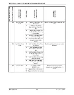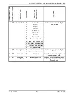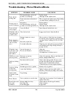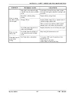
SECTION 3—SAFETY INSPECTION/TROUBLESHOOTING
31
NOTE: This puts a heavy load on the batteries
as they try to push through the stationary
object. If the wheels spin, have two individuals
(one on each arm) apply as much downward
pressure as possible on the arms of the
wheelchair.
7. Read the meter while the motors are
straining, no longer than 3-4 seconds, to
determine the voltage under load.
NOTE: If the voltage drops more than 2.5 volts
from a pair of fully charged batteries while
under load, they should be replaced regardless
of the unloaded voltages. Refer to Replacing
Batteries on page 69.
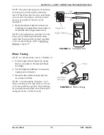
FIGURE 3.1
Motor Testing
NOTE: For this procedure, refer to FIGURE 3.2.
1. On the 4-pin motor connector, locate
the two contacts in the red and black
housings.
2. Set the digital multimeter to measure
resistance in ohms (
Ω
).
3. Measure the resistance between the
two motor contacts.
NOTE: A normal reading is between .5 to 5
ohms. A reading of O.L. (open line) or in excess
of 15 ohms indicates a problem. High readings
are generally caused by bad connections and/or
damaged brushes. Contact Invacare.
FIGURE 3.2
Charger Port
Digital Voltmeter
4 Pin Motor
Connector
Motor
Cap

