SECTION 4—WHEELS AND WHEEL LOCKS
41
Removing/Installing the Caster Assemblies
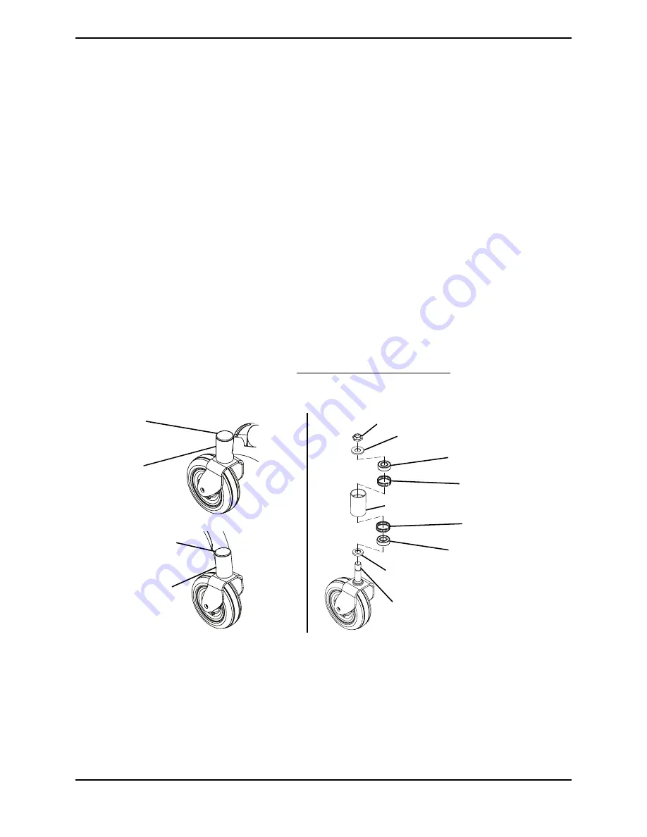
NOTE: For this procedure, refer to FIGURE 4.6.
NOTE: Front and rear caster assemblies are replaced in the same manner.
Removing
1. Remove the head tube cover from the head tube.
2. Remove the 5/8-1/8 locknut, 5/8 x 1-5/16 x 1/8-inch washer and 5/8 x 1-1/8 x 3/16-inch
stem spacer from the threaded post securing the caster assembly to the headtube.
3. If necessary, remove the two bearings and tolerance bearings from the head tube.
Installing
1. If necessary, insert the two bearings and tolerance bearings into the head tube.
2. Insert the threaded post of the caster assembly into the head tube.
3. Using the 5/8-1/8 locknut, 5/8 x 1-5/16 x 1/8-inch washer and 5/8 x 1-1/8 x 3/16-inch
stem spacer, secure the caster assembly to the headtube.
4. Adjust the caster assembly. Refer to Adjusting Caster Assembly on page 40.
5. Insert the head tube cover into the head tube.
FIGURE 4.6
Removing/Installing the Caster Assemblies
5/8-1/8 Locknut
Caster Assembly (Threaded Post)
5/8 x 1-5/16 x 1/8-inch Washer
Head Tube
Head Tube
Cover
5/8 x 1-1/8 x 3/16-inch Stem Spacer
Head Tube Cover
Front Head Tube
Rear Head
Tube
Bearings
Tolerance Bearing
Tolerance Bearing
Bearings

