SECTION 7—REAR FRAME
58
2. Lift the rear frame assembly up and add spacers under the rear casters until the rear
springs remain compressed and the nylon spacer can be removed.
3. Remove the two socket head screws, locknuts, four washers and two nylon stops from
the wheelchair base frame.
NOTE: If necessary, use a flat screwdriver to pry nylon stop from the wheelchair base frame.
4. Remove spacers from under the rear casters.
NOTE: Take note of position and orientation of tie-wraps and wiring prior to removing tie-wraps.
5. Remove the two rear springs.
Installing
NOTE: If replacing the spring, perform this procedure with a new spring.
1. Position the two rear springs between the wheelchair base frame and the rear frame
assembly.
2. Lift the rear frame assembly up and add spacers under the rear casters until the rear
springs remain compressed.
3. Using the two socket head screws, locknuts and four washers, secure the two nylon
stops to the wheelchair base frame. Torque to 75 in-lbs ± 20%.
4. Install the two 5/16-18 locknuts, 5/16 x 5/8 x 1/16-inch washers and nylon stops onto
the two spring brackets. Torque to 75 in-lbs ± 20%.
5. Remove spacers from under the rear casters.
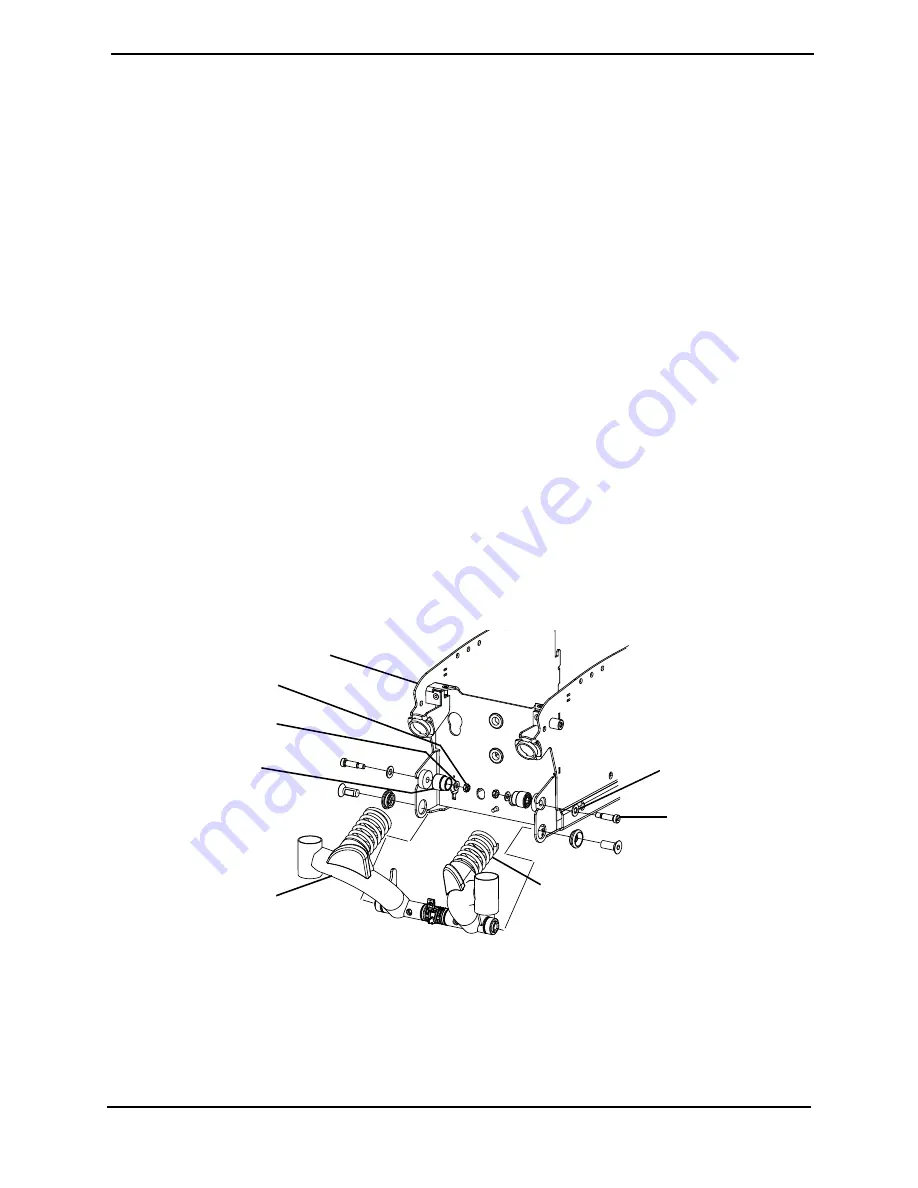
FIGURE 7.2
Removing/Installing the Rear Springs
Rear Suspension
Assembly
Wheelchair Base Frame
3/8 x 1.00 inch
Socket Head
Shoulder Screw
.408 x .807 x .060
Washer
NOTE: Tie-wraps and
wiring not shown.
Nylon Stop
.318 x .625 x .060
Washer
5/16-18 Locknut
Rear Spring


