background image

Part No. 1052712 Rev D

59

Terminator™ SS

LIMITED WARRANTY

PLEASE NOTE: THE WARRANTY BELOW HAS BEEN DRAFTED TO COMPLY WITH

FEDERAL LAW APPLICABLE TO PRODUCTS MANUFACTURED AFTER JULY 4, 1975.
This warranty is extended only to the original purchaser/user of our products.
This warranty gives you specific legal rights and you may also have other legal rights which

vary from state to state.
Invacare warrants the frame to be free from defects in materials and workmanship for a

lifetime of the original purchaser from the date of purchase. All component parts

including, but not limited to camber tubes, caster forks, armrests and upholstery are

warranted against defects in materials and workmanship for a period of one (1) year from

the date of purchase except push handle grips, bushings, bearings, and tires/tubes. If within

such warranty period any such product shall be proven to be defective, such product shall

be repaired or replaced, at Invacare's option. This warranty does not include any labor or

shipping charges incurred in replacement part installation or repair of any such product.

Invacare's sole obligation and your exclusive remedy under this warranty shall be limited to

such repair and/or replacement.
For warranty service, please contact the dealer from whom you purchased your Invacare

product. In the event you do not receive satisfactory warranty service, please write directly

to Invacare Top End at the address on the back page. Provide dealer’s name, address, date

of purchase, indicate nature of the defect and, if the product is serialized, indicate the serial

number. Do not return products to our factory without our prior consent.
LIMITATIONS AND EXCLUSIONS: THE FOREGOING WARRANTY SHALL NOT

APPLY TO SERIAL NUMBERED PRODUCTS IF THE SERIAL NUMBER HAS BEEN

REMOVED OR DEFACED, PRODUCTS SUBJECTED TO NEGLIGENCE, ACCIDENT,

IMPROPER OPERATION, MAINTENANCE OR STORAGE, COMMERCIAL OR

INSTITUTIONAL USE, PRODUCTS MODIFIED WITHOUT INVACARE'S EXPRESS

WRITTEN CONSENT, INCLUDING, BUT NOT LIMITED TO, MODIFICATION

THROUGH THE USE OF UNAUTHORIZED PARTS OR ATTACHMENTS; PRODUCTS

DAMAGED BY REASON OF REPAIRS MADE TO ANY COMPONENT WITHOUT THE

SPECIFIC CONSENT OF INVACARE, OR TO A PRODUCT DAMAGED BY

CIRCUMSTANCES BEYOND INVACARE'S CONTROL, AND SUCH EVALUATION

WILL BE SOLELY DETERMINED BY INVACARE. THE WARRANTY SHALL NOT

APPLY TO PROBLEMS ARISING FROM NORMAL WEAR OR FAILURE TO ADHERE

TO THESE INSTRUCTIONS.
THE FOREGOING EXPRESS WARRANTY IS EXCLUSIVE AND IN LIEU OF ANY

OTHER WARRANTIES WHATSOEVER, WHETHER EXPRESS OR IMPLIED,

INCLUDING THE IMPLIED WARRANTIES OF MERCHANTABILITY AND FITNESS

FOR A PARTICULAR PURPOSE, AND THE SOLE REMEDY FOR VIOLATIONS OF ANY

WARRANTY WHATSOEVER, SHALL BE LIMITED TO REPAIR OR REPLACEMENT OF

THE DEFECTIVE PRODUCT PURSUANT TO THE TERMS CONTAINED HEREIN. THE

APPLICATION OF ANY IMPLIED WARRANTY WHATSOEVER SHALL NOT EXTEND

BEYOND THE DURATION OF THE EXPRESS WARRANTY PROVIDED HEREIN. THE

MANUFACTURER SHALL NOT BE LIABLE FOR ANY CONSEQUENTIAL OR

INCIDENTAL DAMAGES WHATSOEVER.
THIS WARRANTY SHALL BE EXTENDED TO COMPLY WITH STATE/PROVINCIAL

LAWS AND REQUIREMENTS.

WARRANTY

WARRANTY

All manuals and user guides at all-guides.com

Summary of Contents for Top End Terminator SS

Page 1: ...anual Terminator SS DEALER THIS MANUAL MUST BE GIVEN TO THE USER OF THE WHEELCHAIR USER BEFORE USING THIS WHEELCHAIR READ THIS MANUAL AND SAVE FOR FUTURE REFERENCE All manuals and user guides at all g...

Page 2: ...ion of a user while in a wheelchair in a moving vehicle of any type It is Invacare s position that users of wheelchairs should be transferred into appropriate seating in vehicles for transportation an...

Page 3: ...CKS ONLY 23 SECTION 4 SEAT 24 REPLACING TOP END SEAT UPHOLSTERY 24 REPLACING CUSTOM MANUAL SCREW ON SEAT UPHOLSTERY 25 SECTION 5 WHEELS 26 REMOVING INSTALLING REAR WHEELS 26 ADJUSTING QUICK RELEASE AX...

Page 4: ...TALLING ADJUSTING OPTIONAL A4 FOOTREST 47 ANTI TIPPER REPLACEMENT ADJUSTMENT 49 SECTION 7 SUSPENSION 50 ELASTOMERS AND SUSPENSION 50 REPLACING REAR ELASTOMERS 50 REPLACING FRONT ELASTOMERS 52 REMOVING...

Page 5: ...to 5 inches Foot Width 9 to 12 inches average is 10 inches measured between front of footrest bars Footrest Tubular 4 inch Height Adjustable Standard Side Wheel Clearance Adjustable 1 2 to 1 1 2 inche...

Page 6: ...to maintain the proper stability safety and handling of the wheel chair OPERATING INFORMATION WARNING To determine and establish your particular safety limits practice bending reaching and transferrin...

Page 7: ...lchair DO NOT stand on the frame of the wheelchair Check ALL allen screws that secure the footrest raised footrest system to the chair frame BEFORE using the wheelchair ESPECIALLY if engaging in ANY c...

Page 8: ...tire Replacement of the tire or tube MUST be performed by a qualified technician WEIGHT TRAINING WARNING Invacare DOES NOT recommend the use of its wheelchairs as a weight training apparatus Invacare...

Page 9: ...tional safeguard for the wheelchair user Anti tippers MUST BE attached at all times Inasmuch as the anti tippers are an option on this wheelchair You may order with or without the anti tippers Invacar...

Page 10: ...ny change to one 1 or any combination of the five 5 may cause the wheelchair to decrease in stability Use EXTREME caution when using a new seating position The addition of anti tippers may be required...

Page 11: ...S TIPPING WARNING DO NOT tip the wheelchair without assistance DO NOT let the wheelchair drop the last few inches to the ground This could result in injury to the occupant When tipping the wheelchair...

Page 12: ...he ground until the wheelchair has been pulled backward far enough for the front casters to clear the edge of the curb WARNING When lowering the front casters of the wheelchair DO NOT let the wheelcha...

Page 13: ...r to move a wheelchair between floors Serious bodily injury may occur TRANSFERRING TO AND FROM OTHER SEATS WARNING BEFORE attempting to transfer in or out of the wheelchair every precaution should be...

Page 14: ...ee of wear and looseness X X Wheel locks easy to engage X X SEAT AND BACK UPHOLSTERY Inspect for rips or sagging X X Inspect fastening flaps to ensure they securely latch X X REAR WHEELS Quick release...

Page 15: ...is manual WARNING DO NOT use WD 40 3 in 1 oil or other penetrating lubricants on quick release axles or camber inserts Otherwise binding and or damage to the wheelchair may occur 3 Clean quick release...

Page 16: ...back of this manual 7 Periodically check handrims to ensure they are secured to the rear wheels Refer to HANDRIM REPLACEMENT in SECTION 5 of this manual 8 Periodically adjust wheel locks as tires wea...

Page 17: ...cket to the chair frame and back cane NOTE Perform procedure to both sides at the same time 1 Loosen the locknuts and hex screws that secure the back angle bracket to the chair frame and the back cane...

Page 18: ...eat Rail TOP Hex Screw and Locknut Back Cane Indexing Notch Cam Back Angle Bracket Seat Rail TOP Hex Screw and Locknut Back Cane Indexing Notch Cam Back Angle Bracket Seat Rail TOP Hex Screw and Lockn...

Page 19: ...the back center upholstery If hook and loop fastener is NOT secure serious injury may result Adjusting Top End Back Upholstery 1 Unlatch the two 2 fastening flaps that secure the top of the back upho...

Page 20: ...nto the back canes NOTE The fastening flap with logo is for the left back cane NOTE Right and left is determined by sitting in the wheelchair 6 Securely latch the bottom of the back upholstery to the...

Page 21: ...ers that secure the EXISTING back upholstery to the back canes 4 Slide the EXISTING back upholstery down and off the back canes 5 Stand behind the wheelchair and perform the following A Slide anchor l...

Page 22: ...cover over the adjustable back upholstery and secure the fastening straps to the front of the adjustable back upholstery 11 Lay the front portion of the back upholstery cover on the seat pan 12 Adjus...

Page 23: ...HT IN INCHES HOLE NUMBER 11 14 14 18 16 20 1 11 14 16 2 12 15 17 3 13 16 18 4 14 17 19 15 18 20 NOTE Holes are numbered from bottom to top for reference only There are no numbers on the back canes NOT...

Page 24: ...the five 5 fastening flaps hang over the right and left sides of the wheelchair frame NOTE The seat upholstery MUST be posi tioned with the three 3 double sided fasten ing flaps towards the rear of t...

Page 25: ...Remove the twelve 12 phillips screws that secure the existing seat upholstery to the seat frame 3 Remove the existing seat upholstery FIGURE 2 REPLACING CUSTOM MANUAL SCREW ON SEAT UPHOLSTERY SEAT SEC...

Page 26: ...dle of the quad release axle and pull axle and wheel away from the wheelchair 2 Repeat STEP 1 for the opposite rear wheel 3 Reinstall the rear wheels onto the wheelchair by reversing STEPS 1 2 Section...

Page 27: ...detent pin and locking pins of the quick quad release axle are fully released BEFORE operating wheelchair Keep locking pins clean 4 If there is too much movement of the rear wheel assembly in a back...

Page 28: ...G QUAD RELEASE HANDLES FIGURE 4 IN AND OR OUT 1 Remove rear wheel and the quad release axle from the wheelchair Refer to REMOVING INSTALLING REAR WHEELS in this section of the manual 2 Loosen the lock...

Page 29: ...wheel from the wheelchair Refer to REMOVING INSTALLING REAR WHEELS in this section of the manual WARNING Tire MUST be FULLY deflated BEFORE any disassembly procedures are performed Otherwise injury or...

Page 30: ...quick release levers are in the CLOSED position BEFORE using the wheelchair otherwise personal injury or damage to the wheelchair may result WARNING STANDARD CAMBER OR RECEIVER TUBE CLAMPS Make sure t...

Page 31: ...K RELEASE LEVERS Tighten the threaded knob to secure the quick release lever Push the quick release lever on the receiver tube clamps to the closed position B STANDARD RECEIVER TUBE CLAMPS Tighten the...

Page 32: ...there is no more than 3 inches 12 indexing marks of the camber inserts outside of the axle tube 7 Slide the indexing ring on the camber insert until it is flush with the camber clamp NOTE Before usin...

Page 33: ...h 0 1 4 inch for maximum rollability one 1 of two 2 conditions exists A If the back centerline measurement of the rear wheels is SMALLER than the front centerline measurement of the rear wheels a TOE...

Page 34: ...tube is moved from the factory set position or is replaced NOTE Make the following adjustment for one 1 camber at a time 1 Open the camber clamps Refer to OPENING CLOSING CLAMPS in this section of the...

Page 35: ...out measurement is less than 1 2 inch 0 1 4 inch for maximum rollability 7 Rotate either the right or left adjustment ring until the stop on the ring is at the top of the slot in the camber clamp as...

Page 36: ...djustment ring is positioned at the opposite end of the camber clamp WARNING QUICK RELEASE LEVERS Make sure the quick release levers are pointing towards the rear of the wheelchair and are in the CLOS...

Page 37: ...he user and or damage to the wheelchair Refer to FIGURE 13 2 Position the camber system to the desired position on the wheelchair frame LENGTHENING THE WHEELBASE will increase the stability and mainta...

Page 38: ...ing in possible injury to the user or damage to the wheelchair 2 Position camber insert to the desired position Make sure there is no more than 3 inches 12 indexing marks showing of the camber inserts...

Page 39: ...Refer to REMOVING INSTALLING REAR WHEELS in this section of the manual 4 A4 CAMBER SYSTEM ONLY Remove the camber inserts positioned in the axle tube 5 A4 CAMBER SYSTEM ONLY Loosen but do not remove th...

Page 40: ...axle tube resulting in possible injury to the user or damage to the wheelchair 12 A4 CAMBER SYSTEM ONLY Install camber inserts into the NEW axle tube and slide the camber inserts to the position note...

Page 41: ...EEL CAMBER in this section of the manual 1 If necessary open BOTH camber clamps Refer to OPENING CLOSING CLAMPS in this section of the manual 2 Loosen the set screw that secures each toe adjustment ri...

Page 42: ...STEP 17 B TOE IN TOE OUT MEASUREMENT IS NOT WITHIN 1 8 INCH i Repeat STEP 1 ii Loosen the set screw on the right toe adjustment ring iii Repeat STEP 3 iv Repeat STEPS 12 16 until toe in toe out measur...

Page 43: ...Y Install the caster bolt locknut and axle spacers onto the fork in the desired mounting position Tighten securely 4 Repeat STEPS 1 2 for the opposite caster if necessary NOTE If replacing front caste...

Page 44: ...the wheelchair on a flat surface 2 Remove the dust cover on the fork assembly 3 Remove the locknut that secures the front caster fork to the wheelchair frame 4 Position a large right triangle or L squ...

Page 45: ...ce between the WHEEL LOCK SHOE and the REAR WHEEL B Slide the wheel lock along the wheelchair until the measurement is between 5 32 and 5 16 inches C Tighten the wheel lock to the wheelchair frame D R...

Page 46: ...g protruding objects when using this wheelchair ADJUSTING REPLACING STANDARD FOOTREST FIGURE 1 1 Loosen the two 2 allen screws that secure the footrest to the wheelchair frame IF REPLACING THE FOOTRES...

Page 47: ...e EXISTING footrest tubes out of the wheelchair frame and install NEW footrest by reversing this step 3 Position the NEW footrest to a determined height 4 Tighten the two 2 allen screws that secure th...

Page 48: ...ove the four 4 flat screws and locknuts that secure footplate to the footrest tubes NOTE Observe the angle of footplate for reinstallation 2 Move the footplate to one 1 of two 2 positions to accommoda...

Page 49: ...secure the EXISTING anti tipper to the wheelchair frame and remove the EXISTING anti tipper from the wheelchair 2 Insert the NEW anti tipper into the wheelchair Make sure the push pins are fully rele...

Page 50: ...ight NOTE Periodically review the following chart to make sure the rear suspension still corresponds to user s weight USER S WEIGHT IN LBS ELASTOMERS REQUIRED PER SIDE UPPER LOWER Less Than 100 BLUE B...

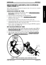
Page 51: ...nto the mounting bolt NOTE It may be necessary to compress the rear suspension system to install the locknut onto the mounting bolt 5 Tighten the locknut until three 3 threads can be seen on the end o...

Page 52: ...ess and the other end into the fork recess DETAIL A NOTE Ensure the ends of the elastomer sit flush in the fork and fork stem recesses 4 Hold and squeeze the fork and fork stem together DETAIL B 5 Ins...

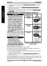
Page 53: ...ENING CLOSING CLAMPS in SECTION 5 of the manual 4 Pull the suspension tubes with rear axle away from the receiver tube 5 Note the mounting position of the two 2 mounting screws and locknuts securing t...

Page 54: ...ing rear wheel size WARNING Forks for quick release casters are available in different sizes to accommodate spacers If the wheelchair is equipped with quick release casters DO NOT adjust seat to floor...

Page 55: ...rmined by standing behind the wheelchair 1 Open both the camber clamps Refer to OPENING CLOSING CLAMPS in PROCEDURE 5 of the manual 2 Remove the rear wheels from the wheelchair Refer to REMOVING INSTA...

Page 56: ...TANDARD B 2 MIDDLE B 1 STANDARD C 2 BOTTOM A 2 INVERTED B 1 NOTE Tabs on camber clamps shown Anti tipper sockets are not shown for clarity NOTE Whenviewedfromthefrontofthewheelchair inside of the rear...

Page 57: ...e the quick release lever recessed washer and coved washer from the camber clamp 3 If necessary position the recessed washer and coved washer onto the quick release lever as shown in FIGURE 6 4 Insert...

Page 58: ...Terminator SS 58 Part No 1052712 Rev D NOTES NOTES NOTES All manuals and user guides at all guides com...

Page 59: ...e of purchase indicate nature of the defect and if the product is serialized indicate the serial number Do not return products to our factory without our prior consent LIMITATIONS AND EXCLUSIONS THE F...

Page 60: ...k of Invacare Top End Sun Metal Products Inc 4501 63RD Circle North KIK is a registered trademark of KIK Pinellas Park FL 33781 Technology Inc 800 532 8677 Spinergy is a registered trademark of Spiner...

Reviews: