background image

Part No. 1110550

43

Tracer® SX5

SECTION 9

SEAT-TO-FLOOR HEIGHT

SEAT-TO-FLOOR 

HEIGHT

Section 9 - Seat-to-Floor Height includes the following:
Changing Seat-To-Floor Height

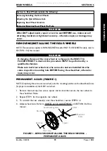
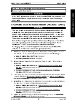
CHANGING SEAT-TO-FLOOR HEIGHT (FIGURES 1 AND 2)

WARNING

The seat depth, size/position of the front casters, size/position of the rear

wheels, use of an anti-tipper model, as well as the user condition directly

relate to the stability of the wheelchair. Any change to one (1) or any com-

bination of the seven (7) may cause the wheelchair to decrease in stability.

These adjustments MUST be performed by a qualified technician.
Seat-to-floor heights have specific positions depending on rear wheel size,

rear wheel position, front caster size and front caster position. These

adjustments MUST be performed by a qualified technician.
If changing the seat-to-floor height the correct anti-tippers MUST be

ordered to maintain a 1-1/2 to 2-inch ground clearance.

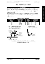
1. Refer to one (1) of the following charts to determine mounting positions for front

casters/forks and rear wheels for the desired obtainable seat-to-floor height:
A.

ADULT/HEMI FRAME STYLE - 

FIGURE 1

B.

RECLINER FRAME STYLE

 - FIGURE 2

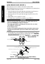
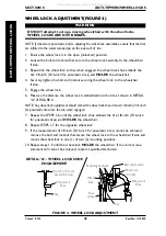
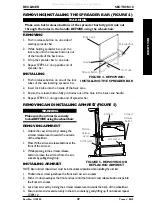
2. Remove the rear wheels from the wheelchair. Refer to one (1) of the following

procedures:
A.

ADULT/HEMI FRAME STYLE - 

REMOVING/INSTALLING THE REAR

WHEELS in SECTION 6 of this manual.

B.

RECLINER FRAME STYLE - 

REMOVING/INSTALLING THE REAR

WHEELS in SECTION 10 of this manual.

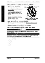
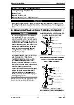
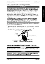
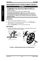
3. If necessary, replace the front casters and forks with the casters and forks indicated

in the chart. Refer to REPLACING FRONT CASTERS and INSTALLING/REPLAC-

ING FORK ASSEMBLIES in SECTION 7 of this manual.

4. Reinstall the rear wheels onto the wheelchair in the mounting position indicated in

the chart. Refer to one (1) of the following procedures.
A.

ADULT/HEMI FRAME STYLE - 

REMOVING/INSTALLING THE REAR

WHEELS in SECTION 6 of this manual.

B.

RECLINER FRAME STYLE - 

REMOVING/INSTALLING THE REAR

WHEELS in SECTION 10 of this manual.

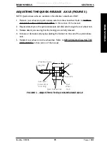
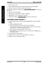
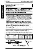
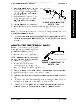
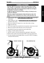
5. Adjust anti-tippers according to NEW seat-to-floor height. Refer to ADJUSTING

THE ANTI-TIPPERS in SECTION 8 of this manual.

WARNING

After ANY adjustments, repair or service and BEFORE use, make sure all

attaching hardware is tightened securely - otherwise injury or damage

may result.

All manuals and user guides at all-guides.com

Summary of Contents for Tracer SX5 Recliner

Page 1: ...R OF THE WHEELCHAIR USER BEFORE USING THIS WHEELCHAIR READ THIS MANUAL AND SAVE FOR FUTURE REFERENCE Owner s Operator And Maintenance Manual Tracer SX5 Tracer SX5 Recliner R R All manuals and user guides at all guides com a l l g u i d e s c o m ...

Page 2: ...UNDERSTANDING THIS MANUAL IF YOU ARE UNABLE TO UNDERSTAND THE WARNINGS CAUTIONS AND INSTRUCTIONS CONTACT A HEALTHCARE PROFESSIONAL DEALER OR A QUALIFIED TECHNICIAN BEFORE ATTEMPTING TO USE THIS EQUIPMENT OTHERWISE INJURY OR DAMAGE MAY RESULT SAVE THESE INSTRUCTIONS All manuals and user guides at all guides com ...

Page 3: ... THE FOOTREST 23 FOOTREST HEIGHT ADJUSTMENT 24 HEEL LOOP REPLACEMENT 24 RAISING LOWERING THE ELEVATING LEGREST ASSEMBLY 25 SECTION 4 ARMS 26 USING OR REPLACING FLIP BACK ARMREST 26 ADJUSTING ARMREST HEIGHT 27 SECTION 5 SEAT AND BACK 28 INSTALLING THE BACK CANES 28 REPLACING BACK UPHOLSTERY 29 REPLACING SEAT UPHOLSTERY 29 ADJUSTING SEAT DEPTH 30 ADJUSTING THE SEAT WIDTH 31 SECTION 6 REAR WHEELS 33 ...

Page 4: ...NER OPERATION 46 REPLACING THE HEADREST PILLOW 48 REPLACING THE HEADREST BACK UPHOLSTERY 48 REMOVING INSTALLING THE SPREADER BAR 49 REMOVING AND INSTALLING ARMREST 49 REMOVING INSTALLING THE REAR WHEELS 50 SECTION 11 OPTIONS 51 INSTALLING THE AMPUTEE BRACKET 51 INSTALLING THE SEAT POSITIONING STRAP 52 INSTALLING THE CRUTCH AND CANE CARRIER 53 INSTALLING THE TELESCOPING I V ROD 54 LIMITED WARRANTY ...

Page 5: ... be transported in ve hicles of any kind while in wheelchairs As of this date the Department of Transportation has not approved any tie down systems for transportation of a user while in a wheelchair in a moving vehicle of any type It is Invacare s position that users of wheelchairs should be transferred into appropriate seating in vehicles for transportation and use be made of the restraints made...

Page 6: ...3 16 for pneumatic tires 3 Tighten mounting fastener to secure mounting bracket in desired location and recheck lock shoe embedding 4 Inspect for correct locking action BEFORE actual use 00078X021 0394 LABEL LOCATIONS LABEL LOCATIONS LABEL LOCATIONS WARNING DETENT BALLS MUST BE SECURE LY SEATED IN RECESSED AREAS OF AXLE BUSHINGS ENSURE THAT PLUNGER PIN IN HEAD END OF AXLE IS FULLY RELEASED KEEP DE...

Page 7: ...ock Caster Size 8x1 1 4 inch Urethane 6 x 1 inch Urethane 8x1 1 4 inch Pneumatic or 8x1 inch Urethane Pneumatic Flat Free Insert 8x1 inch Solid Rubber and 8x1 3 4 inch Semi Pneumatic 8x1 1 4 inch Pneumatic or standard on 20 and 22 inch width Pneumatic Flat Free Insert chairs 8x1 3 4 inch Semi Pneumatic standard on 20 and 22 inch width chairs Upholstery Vinyl Black Nylon Frame Colors Chrome Chrome ...

Page 8: ...when in ANY reclined position Make sure the patient is properly positioned in the wheelchair before reclining or inclining reverse recline to maintain maximum stability and safety Assistants MUST be prepared to support the weight of the occupant when reclining or returning the occupant of the wheelchair to the full upright position Make sure to use proper body mechanics use your legs or seek assis...

Page 9: ...r wheel position front caster size and front caster position These adjustments MUST be performed by a qualified technician Anti tippers are specific to the different seat to floor heights Refer to the chart in INSTALLING ADJUSTING THE ANTI TIPPERS in SECTION 8 of this manual for correct usage and adjustment If these requirements cannot be achieved do not use the wheelchair Contact a qualified tech...

Page 10: ...ON 8 of this manual Always return the back to the upright back at 90 position before lifting the wheelchair OPERATING INFORMATION WARNING All service and adjustments should be performed while the wheelchair is unoccupied After ANY adjustments repair or service and BEFORE use make sure all attaching hardware is tightened securely otherwise injury or damage may result To determine and establish your...

Page 11: ...ance DO NOT use an escalator to move a wheelchair between floors Serious bodily injury may occur Before attempting to transfer in or out of the wheelchair every precau tion should be taken to reduce the gap distance Turn both casters paral lel to the object you are transferring onto When transferring to and from the wheelchair ALWAYS ENGAGE BOTH WHEEL LOCKS DO NOT use parts accessories or adapters...

Page 12: ...G WARNING Invacare DOES NOT recommend the use of its wheelchairs as a weight training apparatus Invacare wheelchairs have NOT been designed or tested as a seat for any kind of weight training If occupant uses said wheelchair as a weight training apparatus Invacare shall NOT be liable for bodily injury and the warranty is void WEIGHT LIMITATION WARNING The Tracer SX5 and Tracer SX5 Recliner wheelch...

Page 13: ...der with or without the Seat Chest Positioning Strap Invacare strongly recommends ordering the Seat Chest Positioning Strap as an additional safeguard for the wheelchair user To assure stability and proper operation of your wheelchair you must at all times maintain proper balance Your wheelchair has been designed to remain upright and stable during normal daily activities as long as you do not mov...

Page 14: ...orward in the seat or pick them up from the floor by reaching down between your knees The seat depth size position of the front casters size position of the rear wheels use of an anti tipper model as well as the user condition directly relate to the stability of the wheelchair Any change to one 1 or any com bination of the seven 7 may cause the wheelchair to decrease in stability These adjustments...

Page 15: ...t Point front casters forward to create the longest possible wheelbase Reach back only as far as your arm will extend without changing your sitting position TIPPING WARNING DO NOT tip the wheelchair without assistance When tipping the wheelchair an assistant should grasp the back of the wheelchair on a non removable non detachable part Inform the wheelchair occupant before tipping the wheel chair ...

Page 16: ...his method requires two 2 assistants The second assistant should be positioned at the front of the wheelchair lifting upward on a non removable non detachable part of the wheelchair frame when lifting the wheelchair and stabilizing the wheelchair when the wheel chair is being lowered to the ground The first assistant should stand on the sidewalk and turn the wheelchair so that the rear wheels are ...

Page 17: ...o moving Invacare recom mends using two 2 assistants and making thorough preparations Make sure to use ONLY secure non detachable parts for hand held supports TRACER SX5 RECLINER ONLY ALWAYS return the back to the upright position before lifting the wheelchair Follow this procedure for moving the wheelchair between floors when an eleva tor is NOT available 1 If necessary rotate the anti tippers so...

Page 18: ...on of the manual TRANSFERRING TO AND FROM OTHER SEATS WARNING BEFORE attempting to transfer in or out of the wheelchair every precau tion should be taken to reduce the gap distance Turn both casters parallel to the object you are trans ferring onto Also be certain the wheel locks are engaged to help prevent the wheels from moving CAUTION When transferring position yourself as far back as possible ...

Page 19: ...nt of the wheelchair 3 Pivot footplates upward to vertical position 4 With both hands grasp the middle of the seat upholstery at the front and back edge and lift up 5 Continue to close the wheelchair by grasping the back cane furthest from you and pulling the armest towards you NOTE If wheelchair is equipped with carry straps the wheelchair may be closed by pulling up on the straps FOLDING UNFOLDI...

Page 20: ...ect reclining mechanisms to ensure they are clean and work freely X X SEAT AND BACK Inspect upholstery for rips or sagging X X Inspect for loose or broken hardware X X Inspect cane hand grips for wear looseness deterioration X X TIRES Inspect for flat spots cracks and wear X X If pneumatic tires check for proper inflation X X CAUTION As with any vehicle the wheels and tires should be checked perio...

Page 21: ...cking and proper operation Refer to ADJUSTING THE QUICK RELEASE AXLE in SECTION 6 of this manual WARNING DO NOT use WD 40 3 in 1 oil or other penetrating lubricants on quick release axles Otherwise binding and or damage to the wheelchair may occur 3 Clean oil quick release axles once 1 a week with a Teflon lubricant WARNING DO NOT use the wheelchair unless it has the proper tire pressure p s i DO ...

Page 22: ...K ADJUST MENT in SECTION 8 of this manual 8 Periodically check caster and rear wheel bearings to make sure they are clean and free from moisture Use a Teflon lubricant if necessary WARNING When cleaning rear cane or hand grip areas use only a clean towel lightly dampened with cool water Verify that grips are dry prior to use Use of soap or ammonia based cleaning solutions will result in the hand g...

Page 23: ... dicular to wheelchair 2 Install the hinge plates on the swing away footrest assembly onto the hinge pins on the wheelchair frame 3 Push the swingaway footrest assembly towards the inside of the wheelchair until it locks into place NOTE The footplate will be on the inside of the wheelchair when locked in place 4 Repeat this procedure for the other footrest assembly 5 To release the footrest push t...

Page 24: ...est and eleveating legrest 1 Remove the swingaway footrest assembly Refer to INSTALLING REMOVING THE SWINGAWAY FOOTREST in this section of the manual NOTE Lay the assembly on a flat surface to simplify this procedure 2 Pull the cam lock lever to UP UN LOCKED position 3 Push IN the release buttons and reposition the lower footrest assembly to the desired height 4 Ensure that the release buttons ful...

Page 25: ...egrests until the desired height is obtained 2 To lower the elevating legrest perform the following A Support user leg with one 1 hand B Push release lever downward with other hand C Gently lower user leg down and rest against the legrest FIGURE 4 ADJUSTING THE ELEVATING LEGREST ASSEMBLY Support Tube Release Lever SECTION 3 FRONT RIGGINGS FRONT RIGGINGS All manuals and user guides at all guides co...

Page 26: ...curelylockedintoarm socketandarmrestreleasebuttonlocksinto placeBEFOREusing REPLACING 1 PerformSTEPS1 2abovetoflipthearmrestback 2 Removehexscrew spacerandlocknutsecuringtheEXISTINGarmrestandinserttothewheel chair frame 3 RemovetheEXISTINGarmrestfromframe 4 InspectreartubeofNEWarmresttoensureinsertisproperlyinstalledwithmountingholesaligned 5 Ifnotproperlyaligned rotatetheinsertusingaflatscrewdriv...

Page 27: ...t of the armrest base to the UP HORIZONTAL position NOTE Height adjustment lever MUST be in the unlocked position when placing armrest into the armrest base 2 Adjust armrest to desired height 3 Lock the armrest by pressing the height adjustment lever into the DOWN VER TICAL position when the desired armrest height is achieved 4 Check that the armrest is locked into position by gently lifting up If...

Page 28: ...e with nut facing the outside of the wheelchair and aligned with the mounting hole in the bottom of the back cane 3 Insert the back cane into the a mounting hole in the wheelchair frame 4 Position the hex screw through the wheelchair frame back cane and threaded insert as shown in FIGURE 1 NOTE The hex screw should be inserted from the INSIDE of the wheelchair frame 5 Torque the hex screw to 60 80...

Page 29: ...ews Washers Washers Back Upholstery REPLACING SEAT UPHOLSTERY FIGURE 3 1 Remove the eight 8 phillips screws and washers that secure the existing seat upholstery to the crossbraces 2 Remove the existing seat upholstery from the crossbraces 3 Ensure positioning of seat positioning strap if used Refer to INSTALLING THE SEAT POSITIONING STRAP in SECTION 11 of this manual 4 Install new seat upholstery ...

Page 30: ...e seat depth of the wheelchair the seat upholstery MUST be changed as well 2 Remove the two 2 plug buttons from the ends of the crossbraces that are towards the front of the wheelchair NOTE The two 2 plug buttons will be used in the ends of the seat extensions 3 Install the two 2 seat extension tubes into the ends on the crossbraces Line up the rear mounting hole of the seat extension tube with th...

Page 31: ... with the existing hex screw coved washers washers and locknut Securely tighten Refer to DETAIL B for hardware orientation 6 Determine the correct pivot link and mounting hole to use with the desired seat width See chart below 16 INCH 18 INCH 14 INCH 20 INCH 22 INCH 14 Inch 16 Inch 18 Inch DO NOT USE 20 Inch 22 Inch 7 Secure the pivot links to the crossbraces and wheelchair frame with the four 4 b...

Page 32: ...ew STEPS 3 8 Crossbrace Saddle STEPS 3 8 Locknut STEPS 3 8 Pivot Link STEPS 2 7 Locknut STEPS 2 7 Locknut STEPS 2 7 Button Screw STEPS 2 7 Wheelchair Frame Locknut STEPS 2 7 Button Screw STEPS 2 7 DETAIL A Button Screw STEPS 2 7 Hex Screw Washer Coved Washers Locknut Washer Coved Washers Washer Coved Washer DETAIL B CROSSBRACE HARDWARE STEPS 4 5 Crossbraces All manuals and user guides at all guide...

Page 33: ...ified technician Make sure both rear wheels are the same size and are installed into the same respective mounting hole BEFORE using the wheelchair otherwise injury may occur PERMANENT AXLES FIGURE 1 NOTE If replacing the same size rear wheel note the mounting position on the wheelchair frame for proper reinstallation of the NEW rear wheel 1 Remove the dust cap hex screw spacer and locknut that sec...

Page 34: ...cking pins of the quick release axle are fully released BEFORE operating the wheelchair The locking pins MUST be protruding past the inside of the rear wheel axle bushing for a positive lock Keep locking pins clean Invacare recommends inserting quick release axles with the detent pin to the inside of the wheelchair to prevent accidental release during contact activities 5 If the locking pins are n...

Page 35: ...rough the rear wheel hub 3 Release detent pin ensuring that the locking pins are fully released 4 Increase or decrease end play by adjusting the locknut on the end of the quick release axle 5 Reinstall rear wheel onto the wheelchair Refer to REMOVING INSTALLING THE REAR WHEELS in this section of the manual Detent Pin Locknut Locking Pins Rear Wheel Hub Quick Release Axle Axle Spacer Conventional A...

Page 36: ...stall the NEW handrim by reversing the above steps 5 Reinstall rear wheel to the wheelchair Refer to REMOVING INSTALLING THE REAR WHEELS in this section of the manual 6 Repeat the procedure for the opposite rear wheel if necessary REPLACING REPAIRING REAR WHEEL TIRE TUBE WARNING WARNING WARNING WARNING WARNING Replacement of rear wheel tire or tube MUST be performed by a quali fied technician CAUT...

Page 37: ...e size BEFORE using the wheelchair otherwise injury may occur NON RECLINER 20 22 WIDE 300 LB WEIGHT LIMITATION WHEELCHAIRS AND ALL RE CLINER MODELS ONLY The factory installed 8 inch fork assem bly part number 1089103 and fork stem washer part number 1089102 MUST be used on wheel chairs of these widths DO NOT replace with any other size style fork assembly Otherwise injury or damage may occur NOTE ...

Page 38: ...S FIGURE 1 1 To properly tighten caster journal system and guard against flutter perform the follow ing check a Tip back of wheelchair to floor b Pivot both forks and casters to top of their arc simultaneously c Let casters drop to bottom of arc wheels should swing once to one side then immediately rest in a straight downward position d Adjust locknuts according to freedom of caster swing e Repeat...

Page 39: ... style front caster Otherwise injury or damage may occur NOTE If replacing the same size front caster note the mounting position on the fork assembly for proper reinstallation of the NEW front caster 1 Remove the hex screw washers and locknut that secure the front caster to the fork NOTE Washers are only used with 6 and 8 inch casters with precision bearings 2 To reinstall the new front caster ont...

Page 40: ...ou may order with or without the anti tippers Invacare strongly recom mends ordering the anti tippers as a safeguard for the wheelchair user RECLINERS ONLY Anti tippers MUST BE attached at all times Anti tippers MUST be fully engaged and release buttons fully protruding out of adjustment holes Ensure both anti tippers are adjusted to the same mounting hole INSTALLING THE ANTI TIPPERS FIGURES 1 AND...

Page 41: ...ippers Refer to ADJUSTING THE ANTI TIPPERS in this section of the manual ADJUSTING THE ANTI TIPPERS FIGURE 3 NOTE A 1 1 2 to 2 inch clearance between the bottom of the anti tipper wheels and the ground floor MUST be maintained at all times 1 Place the wheelchair on a flat surface NOTE If adjusting anti tippers on recliner mod els ensure back canes are in the upright posi tion BEFORE making adjustm...

Page 42: ...URE 4 NOTE Any wheel lock adjustment should embed the wheel lock shoe at least 1 8 inch 3 16 inch for pneumatic tires into the tire when engaged 7 Repeat the STEPS 1 6 until the wheel lock shoe embeds the tire 1 8 inch 3 16 inch for pneumatic tires and HOLDS the wheelchair 8 Repeat STEPS 1 7 for the opposite wheel lock 9 If the measurement of 1 8 inch 3 16 inch for pneumatic tires cannot be achiev...

Page 43: ...r the desired obtainable seat to floor height A ADULT HEMI FRAME STYLE FIGURE 1 B RECLINER FRAME STYLE FIGURE 2 2 Remove the rear wheels from the wheelchair Refer to one 1 of the following procedures A ADULT HEMI FRAME STYLE REMOVING INSTALLING THE REAR WHEELS in SECTION 6 of this manual B RECLINER FRAME STYLE REMOVING INSTALLING THE REAR WHEELS in SECTION 10 of this manual 3 If necessary replace ...

Page 44: ...OP 16 1 2 MIDDLE 22 inch TOP 17 1 2 BOTTOM 24 inch TOP 17 1 2 BOTTOM 20 inch BOTTOM 8 INCH FRONT CASTERS SEAT TO FLOOR FRONT CASTER REAR REAR WHEEL HEIGHT MOUNTING WHEEL MOUNTING in inches POSITION SIZE POSITION 17 1 2 TOP 20 inch BOTTOM 17 1 2 TOP 24 inch TOP 18 1 2 MIDDLE 22 inch BOTTOM 19 1 2 BOTTOM 24 inch BOTTOM NOTE 6 inch and 8 inch front casters require different forks WARNING 20 22 WIDE 3...

Page 45: ... may occur 8 INCH FRONT CASTERS SEAT TO FLOOR FRONT CASTER REAR REAR WHEEL HEIGHT MOUNTING WHEEL MOUNTING in inches POSITION SIZE POSITION 17 1 2 TOP 20 inch N A 18 1 2 MIDDLE 22 inch N A 19 1 2 BOTTOM 24 inch N A SECTION 9 SEAT TO FLOOR HEIGHT SEAT TO FLOOR HEIGHT 8 INCH FORK MOUNTING POSITIONS TOP MIDDLE BOTTOM REAR WHEEL MOUNTING POSITION TRACER SX RECLINER FRAME STYLE Rearward Mounting Positio...

Page 46: ...rude out through the hole in the handle BEFORE using the wheelchair Make sure both back canes are at the same angle BEFORE releasing the handles of the recline mechanisms Mount the rear wheels in the Rear Wheel Offset Bracket ONLY NEVER reposition the rear wheels to the forward position stability of the wheel chair will decrease Before using the recliner option the anti tippers MUST be installed a...

Page 47: ...VING INSTALLING THE SPREADER BAR in this section of the manual 3 Make sure wheelchair is occupied and on a level surface before reclining 4 Engage the wheel locks 5 Inform the occupant of the wheelchair that the wheelchair is about to be reclined 6 Make sure occupant s hands and body are clear of all pinch points 7 Stand behind the wheelchair and grasp both push handles firmly 8 Lifting up on hand...

Page 48: ...ews 4 Install headrest pillow Refer to REPLAC ING THE HEADREST PILLOW in this section of the manual BACK UPHOLSTERY 1 Disengage one 1 side of the spreader bar Refer to REMOVING INSTALLING THE SPREADER BAR in this section of the manual NOTE To remove and install the bottom two 2 mounting screws of the back upholstery the wheelchair must be partially folded Refer to SAFETY HANDLING OF WHEELCHAIRS in...

Page 49: ...ked BEFORE using the wheelchair REMOVING ARMREST 1 Unlock the rear armrest by rotating the armrest release lever towards the outside of the wheelchair 1 Press IN the armrest release buttons at the front of the armrest 2 While pressing in the armrest release button remove the armrest from the arm sockets by pulling straight up INSTALLING ARMREST NOTE Rear armrest release lever must be in the unlock...

Page 50: ...ry or damage may result REMOVING 1 Note mounting position of EXISTING rear wheel 2 Remove the axle mounting screw and locknut that secure the EXISTING rear wheel and spacer to the wheel offset bracket 3 Remove the EXISTING rear wheel from wheel offset bracket INSTALLING 1 Secure the new existing rear wheel and spacer to wheel offset bracket with axle mounting screw and locknut Securely tighten REC...

Page 51: ...n determined in STEP 1 NOTE Make sure the axle spacer is located to the outside of the wheelchair 3 Install the two 2 hex screws and locknuts that secure the amputee bracket to the wheelchair 4 Install the rear wheels onto the wheelchair Refer to REMOVING INSTALLING THE REAR WHEELS in SECTION 6 of this manual OPTIONS SECTION 11 OPTIONS FIGURE 1 INSTALLING THE AMPUTEE BRACKET REAR VIEW OF AMPUTEE B...

Page 52: ...the wheelchair user 1 Remove the rear seat upholstery screw from the wheelchair 2 Position one seat positioning strap half between the seat rail and seat upholstery 3 Secure the seat upholstery and seat positioning strap to the wheelchair with the existing seat upholstery screw 4 Repeat STEPS 1 3 for the opposite side of the wheelchair OPTIONS SECTION 11 OPTIONS FIGURE 2 INSTALLING THE SEAT POSITI...

Page 53: ...se should be parallel to step tube to avoid bending spokes when folding the wheelchair 3 Securely tighten the locknut that secures the base to the step tube of the wheelchair 4 Remove the upper back upholstery screw and washer 5 Align the strap with the back upholstery screw mounting hole 6 Reinstall the back upholstery screw and washer and secure the strap to the wheelchair 7 The base cleans easi...

Page 54: ...I V rod mounting bracket on the step tube on the side determined in STEP 1 3 Loosely install the lug screw spacer and locknut that secure the mounting bracket to the back cane 4 Remove the top phillips screw and washer from the back upholstery 5 Line up the mounting holes in the back cane back upholstery and upper attachment 6 Reinstall the washer and phillips screw and securely tighten 7 Securely...

Page 55: ...P 3 Step Tube Phillips Screw Upper Attachment Adjustment Knob Back Upholstery MOUNTING THE I V ROD ON THE LEFT SIDE Washer Washer Phillips Screw Upper Attachment MOUNTING THE I V ROD ON THE RIGHT SIDE Back Upholstery Back Cane Back Cane Outer Tube Upper Attachment Shown rotated 180 Height Adjustment Assembly Hole PhillipsScrew Inner Tube Outer Tube DETAIL A REPOSITIONING THE UPPER ATTACHMENT All m...

Page 56: ...e satisfactory warranty service please write directly to Invacare at the address at the bottom of this page Provide dealer s name address the product model number date of purchase indicate nature of the defect and if the product is serialized indicate the serial number Do not return products to our factory without our prior consent LIMITATIONS AND EXCLUSIONS THE FOREGOING WARRANTY SHALL NOT APPLY ...

Reviews: