background image

This symbol means warning.

!

If the instruction is not followed, damage may be caused to 
the person and/or the product.

•    Check the following before using the wheelchair:
     - that all parts are attached securely to the frame
     - that all levers and knobs are securely tightened
     - that all brakes and anti-tip devices work
•    Always lift the wheelchair according to the instructions. 

See page 3.

•    Always apply the brake to the wheelchair before the 

user gets into or out of the chair.

•    Remember  that  the  handrims  may  become  hot  as  a 

result of friction and may cause damage to the user’s 
hands.

•    Angle adjustment of the seat increases the risk of tip-

ping.

•    Use the anti-tip devices are much as possible.
•    Remember  that  the  effectiveness  of  the  brakes  is 

reduced on wet and slippery surfaces or on downward 
slopes.

•    Ensure that the drive wheels are securely attached. .
•    The rear wheels must not be removed when the user 

is sitting in the chair.

•    As regards adjustable backrest upholstery, the risk of the 

wheelchair tipping is increased the more that the Velcro 
strips on the backrest upholstery are slackened.

•    Risk of tipping over when bags are hanged on the back-

rest.

Invacare Rea AB

Växjövägen 303 S-343 71  DIÖ SWEDEN

Sales companies:

Manufacturer:

Ar

t.nr 1428256  02.1213

Belgium:

Invacare n.v.
Autobaan 14
B-8210 Loppern, Brügge
Tel. +32 - 50 83 10 10
Fax. +32 - 50 83 10 11

Denmark:

Invacare A/S
Sdr. Ringvej 39
DK-2605 Brøndby
Tel.  +45 - 36 90 00 00
Fax. +45 - 36 90 00 01

Finland:

Inva Apuväline OY
Kumpulantie 1
00520 HELSINKI
Tel. +358 (09) 22 95 40
Fax. +358 (09) 229 
544 04

France

Invacare Poirier S.A
Les Roches
F.37230 Fondettes
Tel. +33 - 02 47 62 64 66
Fax. +33 - 02 47 62 64 10

Germany:

Austria, Switzerland 

and Eastern Europe

Invacare GmbH
Dehmer Strasse 66
D-32549 Bad Oeynhausen
Tel. +49 - 57 31 754 0
Fax. +49 - 57 31 754 150

Holland:

Invacare B.V.
Celsiusstraat 46 / P.O. Box 123
NL-6710 BC Ede
Tel. +31 - 318 695757
Fax. +31 - 318 695758

Italy:

Mecc san SARL
Via Ddei Pini, 64
IT- 36016 Thiene VI
Tel. +39 - 445 380059
Fax. +39 - 445 380034

Norway:

Invacare AS
Grensevingen 9
P.O. Box 6230 / Etterstad
N-0603 OSLO 6
Tel. +47 - 22 57 95 00 
Fax. +47 - 22 57 95 01

Portugal:

Invacare Lda
Rua Senhora de Cam-
panhâ
PT- 4369-001 Porto
Tel. +35 - 12 510 59 46 
Fax. +35 - 12 510 57 39

Spain:

Invacare S.A
C/Areny, s/n
Polígon Industrial de Celerá
S- 17460 Celrá (Girona)
Tel. +34 - 972 493200
Fax. +34 - 972 493220

Sweden:

Invacare AB
Fagerstagatan 9 / Box 66
S-163 91 Spånga
Tel. +46 - 8 761 70 90
Fax. +46 - 8 761 81 08

United Kingdom:

Invacare (UK) Ltd.
South Road, Bridgend Indu-
strial Estate 
Bridgend
County Borough of Bridgend 
CF31 3PY
United Kingdom
Tel.: +44 1656 664 321
Fax.: +44 1656 667 532

Summary of Contents for Wheeler

Page 1: ...Wheeler Manual English...

Page 2: ......

Page 3: ...instructions for using Wheeler This manual includes a description of the parts of the chair simple adjustment options how to useWheeler safely and how to transport the chair It also describes how the...

Page 4: ...2 WHEELER...

Page 5: ...stors Always lift the wheelchair by gripping the frame at the points shown in the diagram This applies irrespective of whether the user is or is not in the chair Never lift the wheelchair by the remov...

Page 6: ...tions It is possible that some of the accessories are not available in certain countries Seat unit Adjustable backrest Adjustable seat Comfort backrest Comfort seat Seating pad standard 3 cm Extra sea...

Page 7: ...ansport weight Seat unit 5 kg Chassis 5 kg Drive wheels 4 kg 3 cm Miscellaneous Armrest with padded tubing or wide armrest pad Side guard Push handles or push bar Headrest simple or shaped Pump Mudgua...

Page 8: ...d whilst you insert the axle C into the rear wheel attachment of the positioning plate To check that the wheel has been properly secu red try to pull out the wheel after releasing the button This shou...

Page 9: ...child should be able to hold his or her head upright Angle For most children the angle of the backrest is to be at 90 to the seating surface If the child cannot hold up his or her head the backrest ca...

Page 10: ...ews B are then loosened on both sides of the armrest attachment on both sides of the chair Take hold of the legrest tube C and pull the seat forwards or backwards and then retighten the screws Finally...

Page 11: ...1 5 cm 1 5 cm 1 5 cm Side guards 2 Loosen the screw A under the side guard on both sides Move the side guard outwards Tighten the screws Drive wheels 3 Loosen the axle housing nut C using a spanner E...

Page 12: ...EELER Reduce seat width Hip supports 1 The hip support can be adjusted by adding a cushion to it Open the zip of the hip support and insert the thicker cushion that is included in delivery 1 5 cm 1 5...

Page 13: ...w posi tion Axle D should be fitted so two millimeters Then fit axle D in the new position and retighten the screw Tip Angle the seat backwards so that the foot plate is free of the lower frame tubes...

Page 14: ...the Velcro strips the shape can be adjusted to meet the user s needs for support and comfort For example the strips in the small of the back can be tightened to provide good support for the small of t...

Page 15: ...e seat unit by squeezing the left hand lever D upwards holding it pressed upwards and moving the backrest away from you or towards you until the required position is obtained Then release the lever Fo...

Page 16: ...and remove the screws A from the lower seat attachment behind the drive wheel plate on both sides of the chair Move the attachment to the new position and retighten the screws to secure it in place T...

Page 17: ...of the chair Move the seat to the required position and tighten the screws Use the anti tip devices to assist you when you test to find the right balance position Check that the child can manage the...

Page 18: ...what you think is best If gas pistons are used for angle adjustment of the seat the rear stable position is to be used as the balance is changed when the angle is adjusted Note that the chair can als...

Page 19: ...17 WHEELER CASTORS 1 To move the castor loosen the screw A Keep the nut steady with a spanner Move the wheel to the required position fit the screw and tighten 1 A...

Page 20: ...be fitted in the rear notch for 22 wheels in the middle notch and for 20 wheels in the innermost notch The only time that you need to move the rear wheel plate is when you change the size of rear whe...

Page 21: ...to the required position Retighten the screws C There is to be a distance of 3 mm between pin B and tyre D Incorrect setting or use of the brake impairs the brake effect 1 Apply the brake when pushin...

Page 22: ...ng the push bar push handles upwards or downwards until you obtain the required height Tighten the knobs A 1 The push handles push bar must not leave the notched part of the tubing This is to ensure t...

Page 23: ...ou have changed the wheel position 1 2 If you need to fold away the anti tip devices you can do this using your foot Place your foot on the stem B and move the whole anti tip device backwards so that...

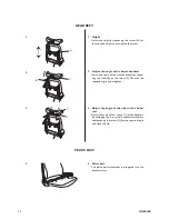
Page 24: ...of the sides of the head rest Adjust the angle of the wings C of the headrest by unzipping the zip at the headrest attachment and loosening the screw D Set the required angle and close the zip 1 Heigh...

Page 25: ...wash Remove them by unzipping the zips and pulling the covers off the pads 1 WASHING UPHOLSTERY 1 2 3 2 The depth of the trunk supports can be adjusted by loosening the screws B Then move the support...

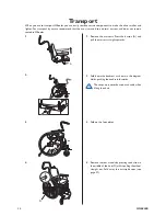
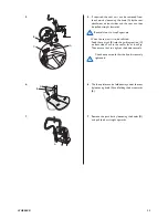
Page 26: ...recommend that the user is moved to a normal car seat and does not remain seated in Wheeler 1 2 2 Fold down the backrest as shown in the diagram whilst pushing the backrest forwards The straps must ne...

Page 27: ...at unit is to be refitted Feed the seat rail B into the guiding section C on both sides Push in the seat as far as it will go Then ensure that you tighten the knob securely Check once a month that the...

Page 28: ...and most suitable for its purpose on the market and we have chosen Unwin s 4 point safety restraint for wheelchairs in combination with a 3 point double inertia reel harness We cannot comment on other...

Page 29: ...secured and transported To reduce the risk of loose objects becoming dislodged and injuring the passengers during trans port the tray and pommel must be removed and secured separately in the vehicle...

Page 30: ...t straps by pulling the wheelchair backwards from the rear Re apply wheelchair brakes C Rear restraints 1 Attach the snap hooks on the rear straps to the transport attachments on the rear frame 3 Tigh...

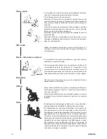
Page 31: ...ways lean forwards whilst propelling up a slope Propel the wheelchair forwards using short quick strokes applied to the hand rims in order to maintain speed and steering control Generally help is need...

Page 32: ...nt to use his or her body correctly to prevent injury Tip the wheelchair backwards and roll the chair over the kerb onto the pavement Take particular care if the kerb is wet or slippery Escalators Do...

Page 33: ...and teenagers It is designed for users who actively use the wheelchair for a long period several hours at a time and for users who need the chair for shorter times and for transport Wheeler is easy to...

Page 34: ...al servicing Only original parts or those approved and fulfilling Invacare s specifications may be used All technical servicing is to be carried out by an authorised wheelchair technician or by Invaca...

Page 35: ...SWEDEN Sales companies Manufacturer Art nr 1428256 02 1213 Belgium Invacare n v Autobaan 14 B 8210 Loppern Br gge Tel 32 50 83 10 10 Fax 32 50 83 10 11 Denmark Invacare A S Sdr Ringvej 39 DK 2605 Br...

Reviews: