11
Document Number
DCV-00214
Date Released
Mar. 2017
Revision Number/Security level
R00 S2
Retrofit G6+InvencoLink GVR Encore 500S (US) Installation Guide
4 Installation Guide
1. Please ensure all safety procedures are followed per requirement by the customer before
installing the retrofit kit.
2. Remove power to Pump and follow the OSHA Lock-out/Tag-out procedures.
3.
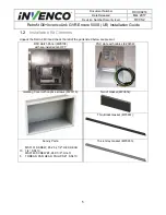
This installation will require various panel replacements. The panels will be removed from the
door and replaced with pre-built panels with the OPT modules pre-fitted.
4.1
Disassembly Procedure
Before installation of the equipment can take place, the existing electronic payment assembly must be
removed from the dispenser. This section covers the removal of these components including:
•
CIM panel and attached components (Display, Keypad, etc)
•
Card Reader and Plate
•
CRIND Control Board & Mounting Bracket
Note
: Throughout this disassembly procedure there are many cable assemblies that will be unplugged
and will not be reused. It is up to the discretion of the installer whether to remove these cables or position
them inside of the dispenser cavity in as to not cause obstruction.
Note:
It may be necessary to unplug a cable assembly on various boards such as the totalizer board or
Door Node to remove other CRIND related cable assemblies. Unplug these cables as necessary and re-
plug them in immediately afterwards. It is recommended that the installer of this kit marks each unplugged
cable after it is unplugged to make it is easier to identify them when it comes time for re-installation.
1.
At the main disconnect panel, disconnect all power to the dispenser and the pump servicing the
dispenser. Tag all disconnected breakers to prevent others from reconnecting power.
2.
Identify the A Side of the dispenser.
Note
:
For the purposes of this manual, Side A of the dispenser refers to the side with the
weights & measures tag on the inside of the electronics cabinet. You may need to open both
doors to determine which is Side A. See steps 3-5 below.
3.
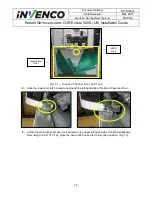
Unlock and remove the panel door with the “GBCO” key. Set it aside. Do not discard the lower
door. It will be re-installed later during the installation procedure. (Fig 1.1)
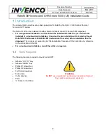
Failure to turn off the unit during installation of the kit may cause injury or bodily harm from electrical shock.
Ensure that all power to the unit is switched off before opening the door of the unit and during kit installation.
WARNING


