30
Document Number
DCV-00214
Date Released
Mar. 2017
Revision Number/Security level
R00 S2
Retrofit G6+InvencoLink GVR Encore 500S (US) Installation Guide
4.3
Installation Procedure
This section follows from the Disassembly procedure above, and assumes the pump is still open.
References to “left-hand” and “right-hand” are as viewed into the pump on the Side you’re working on.
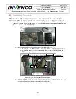
1. Install the EZ0408 PSU Plate assembly. For Side A this is the PSU Plate Assembly that has just
had the InvencoLink converter installed.
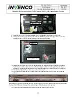
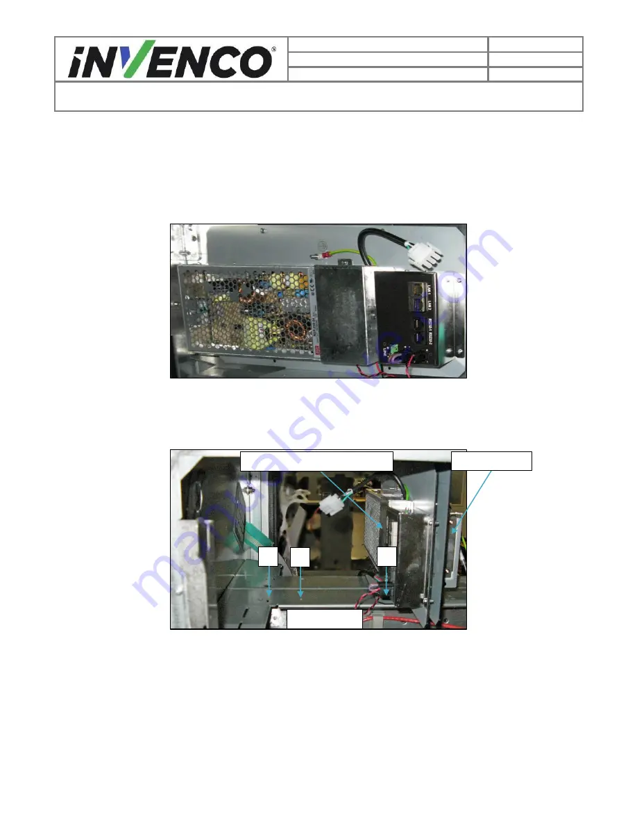
a. Mount the EZ0408 PSU Plate Assembly on the upper electronics rail.
i. For Side A, in the third set of holes from the left side of the dispenser as shown.
ii. For Side B, beside the Side A assembly, back to back in the next holes, as
shown:
Looking from the B-Side of the dispenser
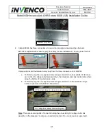
b. Place an MN0031
#8 LockNut on each stud and tighten with a 5/16” nut driver. Note you
will need to place one nut from each side of the dispenser.
Side A EZ0408, with InvencoLink
Side B EZ0408
Hole Positions
1
2
3

