38
Document Number
DCV-00214
Date Released
Mar. 2017
Revision Number/Security level
R00 S2
Retrofit G6+InvencoLink GVR Encore 500S (US) Installation Guide
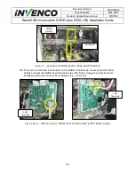
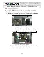
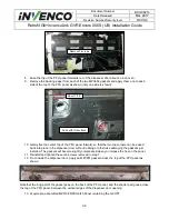
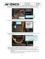
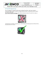
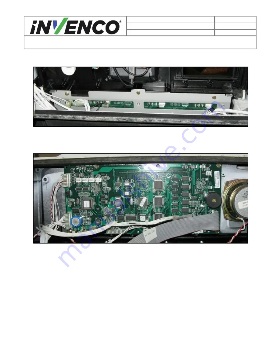
21. Press the PPU circuit board gently back into place against the Encore 500S pump door, then
insert three MS0150 hex-
headed screws. Tighten the screws with a ¼” nut driver.
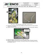
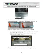
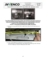
22. Take the Door Node from inside the Encore 500S cabinet and place it back onto the pump door in
the correct position. Insert the
four ¼”-headed screws from Disassembly Step 16 in the corner
holes of the Door Node board.
Tighten the screws with a ¼” nut driver.
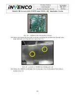
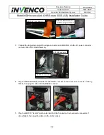
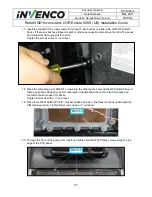
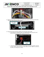
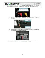
23. Gather the following cables:
a. EK0129 Red patch cable
b. EK0131 Yellow patch cable
c. Black DC and green/yellow earth cable pre-installed on EZ0408 PSU Plate Assembly
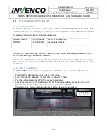
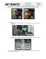
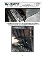
24. Route the four cables from Step 23 along underneath the electronics shelf to the right-hand side
of the pump cabinet, then out along the right-hand side of the cabinet.

