17
Document Number
DCV-00206
Date Released
Dec. 2016
Revision Number/Security level
R00 S2
Retrofit G7+InvencoLink Wayne Ovation (US) Installation Guide
10.
Remove the QVGA Panel.
Note:
There are two different dispenser configurations in which each one involves different steps
in order to remove the QVGA Panel. Setup 1 involves removing the QCAT board, then the QVGA
Retainer Bracket and Display Glass, then the QVGA Panel. Setup 2 involves only removing the
QVGA Panel, leaving the QCAT Board, QVGA Retainer Bracket, and Display Glass intact and
fastened to the QVGA Panel. Follow the appropriate steps according to your dispenser setup.
Removal of QVGA Panel (Setup 1
)
1) Remove and discard the four
#6 ¼” screws (may be fewer after removal of ground
screws) that fasten the QCAT board to the metal QVGA retainer bracket and remove the
board from the retainer assembly. The "Caution High Voltage" shield may need to be
removed to access one of the screws. The QCAT board can be discarded. It will not be
re-installed. (Fig 8a,b)
Note
: the QCAT board may have plastic standoffs in addition to or in substitute of screws. If
so, those standoffs should also be discarded.
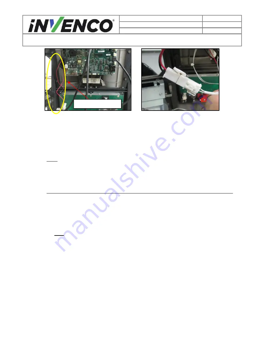
Peripheral Cables
Fig 7a
–
Example of possible existing
peripheral cables
Fig 7b
–
Terminal connecting
peripheral power


