background image

User Manual

XC2907-A Portable Reader

17

 Notes: After Demo is turned on, only when the main page of the demo software 

is pressed, can the card reading operation be carried out or the card reading 

operation be stopped. The other interface side keys are invalid. 

6.4 Main operating instructions for demo software 

6.4.1 Scan Setting 

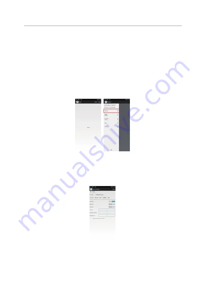
The entry method of the scan settings interface is "Menu" and "Scan Settings", 

as shown in Figure 6-3:

Figure 6-3 Scan settings 

The main function of scanning setting is to set read tag type, read area, read 

length, see Figure 6-4 for details: 

Figure 6-4 Scan settings 

1) Save: When the settings are complete, click "Save" to save the setting data. 

6.  Introduction for RFID module

Summary of Contents for XC2907-A

Page 1: ...User s Manual XC2907 A Portable Reader Invengo Information Technology Co Ltd ...

Page 2: ...ng Invengo s RFID products We are very glad that you chose this XC2907 A portable reader We hope that the equipment can facilitate your work The picture is for reference only and the physical product shall be subject to ...

Page 3: ...l as other information are up to date and valid information All information is accurate when printed INVENGO reserves the right to correct or change the information and instructions in this manual without prior notice or any liability Because of your special needs some features of the product will vary depending on the configuration Safety Instructions Warning sign If operate improperly it may res...

Page 4: ...Dimensions and weight 5 3 1 Dimensions 5 3 2 Weight 6 4 Structural characteristics and operating principle 6 4 1 Appearance description 6 4 2 Installation and removal of battery 7 4 3 Shutdown Standby Restart 7 5 Common functions and settings 8 5 1 Data synchronization between installing USB drive and PC 8 5 2 Backlight regulation 9 5 3 Volume and sound 9 5 4 Instructions for All Netcom Network da...

Page 5: ...of RFID module 14 6 2 Instructions for API interface program 15 6 3 Instructions for demo software 15 6 3 1 Demo software application environment 15 6 3 2 Software installation and start up 15 6 3 3 Software running 16 6 4 Main operating instructions for demo software 17 6 4 1 Scan Setting 17 6 4 2 Power setting 18 6 4 3 Tag filter configuration 19 6 4 4 Search the tag 20 6 4 5 Session configurati...

Page 6: ...aintenance and troubleshooting 30 9 1 Routine maintenance 30 9 2 Analysis and troubleshooting of common problems 31 9 3 RF communication optimization 32 9 3 1 Signal interference problem 33 9 3 2 Information attenuation reflection 33 10 Transport and storage 35 10 1 Transport requirements 35 10 2 Storage requirements 35 11 Packing and unpacking inspection 36 11 1 Packing descriptions 36 11 2 Unpac...

Page 7: ...th fast processing speed good portability and high functional integration Figure 1 1 XC2907 A portable reader 1 2 Main usage and application scope With abundant functions XC2907 A portable reader can be widely applied in multiple fields such as clothing retail warehouse management asset management textile washing etc 1 3 Working environment and conditions XC2907 A portable reader has the following...

Page 8: ...cerned The work of the equipment may interfere with other electronic equipment 2 Performance parameters 2 1 Main functions Support EPC Global UHF Class 1 Gen 2 ISO18000 6C and ISO1800 6B protocols Support the wireless transmission of data information via 4G network data Wi Fi Bluetooth etc Support GPS positioning Support the identification and reading of mainstream 1D and 2D barcodes Support the c...

Page 9: ... environment Android 10 0 SDK INVENGO software development kit Development language Java Development tool Eclipse Android Studio Application software RFID Demo barcode demo software Barcode demo software UHF RFID module Support protocol EPC Global UHF Class 1 Gen 2 ISO18000 6C ISO1800 6B Working frequency 920 925MHz Output power 0dBm 30dBm stepping 1dB Debug mode PR ASK Read write distance 0 10 0m...

Page 10: ...ion GPS positioning GPS Beidou optional Error 5m Barcode engine Support code system 1D code system Code39 Code93 Code128 Codebar EAN 13 EAN 8 UPC A UPC E ITF14 UCC EAN 128 ITF25 Matrix25 EAN 128 ISBN etc 2D code system PDF417 MicroPDF417 Composite RSS TLC 39 Datamatrix QRcode MicroQRcode Aztec MaxiCode PostalCodes USPostNet USPlanet UKPostal AustralianPostal JapanPostal DutchPostal etc Camera modu...

Page 11: ...95 non condensing 25 Vibration resistance GB T 2423 10 2008 Acceleration 4 9m s2 Frequency range 5Hz 100Hz Driving amplitude peak mm 25 f f 5Hz 10Hz 250 f2 f 10Hz 100Hz Accessories Power adapter DC 5V 2A USB cable 3 Dimensions and weight 3 1 Dimensions XC2907 A portable reader is delicate and beautiful The external dimensions are shown in Figure 3 1 Length width height 170mm 103mm 150mm Figure 3 1...

Page 12: ...iple This chapter mainly details the composition of XC2907 A portable reader the internal structure of components and the working principle and interface description of each module 4 1 Appearance description The front view of XC2907 A portable reader is shown in Figure 4 1 Figure 4 1 Front view of XC2907 A portable reader 1 Camera and barcode Both modules are configuration modules Barcode module p...

Page 13: ...nning function keys 4 2 Installation and removal of battery Battery installation Place the battery press down diagonally into the handle and tighten two screws Battery removal Unscrew the nut remove the handle obliquely upward and take out the battery obliquely upward 4 3 Shutdown Standby Restart Startup Standby Wake up In the shutdown mode long press the left power key of XC2907 A portable reader...

Page 14: ...ommon functions and settings 5 1 Data synchronization between installing USB drive and PC XC2907 A portable reader is connected to PC of Win7 and above system via the attached USB connecting line The system will automatically install the driver to complete the connection process If it is a WinXP system you need to manually install the driver to connect it After successful connection you can view t...

Page 15: ... in Figure 5 2 Figure 5 2 Brightness control 5 3 Volume and sound During the equipment use process the user may adjust the volume as needed and enter the volume control interface through setting and prompt tone and notice As shown in Figure 5 3 The alarm clock and ringtone volume are set in the selected mode Multimedia volume is the last setting in the prompt tone and notification interface Multim...

Page 16: ...t Connection settings Back to the main interface and scroll down the screen it will see the automatic acquisition of the network connection A long press the network icon it will enter the mobile data interface as shown in Figure 5 4 Figure 5 4 Network opening 5 5 Wi Fi instructions Wi Fi function is configured to extend the wireless WLAN transmission function The following is an introduction to co...

Page 17: ...connection setting 5 6 Instructions for Bluetooth This equipment configures Bluetooth The following is an introduction to common operations Opening settings Slide the screen twice in the main interface click the Bluetooth button and turn on Bluetooth As shown in Figure 5 7 Figure 5 7 Bluetooth opening Connection settings When the Bluetooth module is turned on click the Settings and Bluetooth inter...

Page 18: ...lick the screen on both sides of the main interface click position information button to successfully open GPS function The interface is shown in Figure 5 9 Figure 5 9 GPS Opening 5 8 Instructions for barcode module 5 8 1 Technical specification and support format for barcode engine QR code Scanning Angle 40 Scanning mode trigger mode interrupt mode Readable code system ...

Page 19: ...method of barcode module refers to the RFID Reader Universal API Technical Reference Manual In order to ensure the correct reading rate and reading response time please ensure the barcode window of XC2907 A portable reader is 20 30cm from the target barcode When the barcode is printed on a smooth reflective object keep the barcode window and the target barcode at an angle of 15 to 30 before readin...

Page 20: ...00 6C and ISO18000 6B protocols It is suitable for mixed use of different protocols 6 1 2 Technical parameters of RFID module Frequency 902MHz 928MHz Modulation mode ASK modulation Working mode Fixed frequency mode frequency hopping mode Read tag distance 0m 10m relevant to the power and tag environment Write tag distance 0m 5m relevant to the power and tag environment UHF Antenna Direction of pol...

Page 21: ...turer code 12 bit tag model 12 bit tag SN Label manufacturers have different capacities 6 2 Instructions for API interface program API application interface is the middle layer between XC2907 A portable reader and background application software which provides a software interface for user secondary development About API application interface program call and application software development refer...

Page 22: ...hown in Figure 6 2 Figure 6 2 Main page of demo software 1 Menu key Click on the menu key to pop up the system menu 2 Start key Click the start key to start reading the tag and click again to stop reading the tag You can read the tag by side key Press once to start reading the tag and press once to stop reading the tag 3 Clear key Clear the data content displayed in the data display area 4 Data di...

Page 23: ... are invalid 6 4 Main operating instructions for demo software 6 4 1 Scan Setting The entry method of the scan settings interface is Menu and Scan Settings as shown in Figure 6 3 Figure 6 3 Scan settings The main function of scanning setting is to set read tag type read area read length see Figure 6 4 for details Figure 6 4 Scan settings 1 Save When the settings are complete click Save to save the...

Page 24: ...ags GB Only read GB tag XC2907 A does not support the operation 6 Read EPC Only read EPC area of the tag 7 Read TID Only read TID area of the tag 8 General reading Read EPC TID and user area 9 TID Length Set the TID length to be read 10 User data initial address Set the initial address to read the user area 11 User data length Set the reading length of data in the user area Notes TID length user f...

Page 25: ... Tag filter configuration The mode to enter the tag filter configuration is Menu and Tag Filter Configuration The detailed introduction can be shown in Figure 6 6 Figure 6 6 Tag Filter Configuration 1 Configuration Configure as per the interval time that has been entered 2 Cancellation Cancel the Tag Filter Setting 3 Interval time Set the repeated tag filtering time the time is 0s 6553 5s 6 Introd...

Page 26: ...pe The search location is TID or EPC 3 First address Search the first address of the tag 4 Match data The content to search tag 6 4 5 Session configuration The mode to enter the search tag is Menu More Session Configuration the detailed introduction can be shown in Figure 6 8 The recommended configuration for reading multiple tags is session S1 A symbol Figure 6 8 Session Configuration 6 Introduct...

Page 27: ...e Q Value Configuration the detailed introduction can be shown in Figure 6 9 Q value recommended configuration 3 5 Figure 6 9 Q Value Configuration 1 Configuration Save the parameter being set 2 Inquiry Query the parameters that have been set 3 Static Q value The Q value is associated with the number of pre read tags and the starting Q value can be set here 7 Tag operation The mode to enter the ta...

Page 28: ...ce 7 1 Writing EPC The entry mode of writing EPC is tag operation and writing EPC the detailed introduction can be shown in Figure 7 2 Figure 7 2 Writing EPC 1 Write in Write EPC as per the input content 2 Access password Enter the tag access password 3 EPC Length Enter the length to be written 4 EPC data Enter the content to be written 7 Tag operation ...

Page 29: ...d User Data 1 Read Read the data pursuant to the filling content 2 First address Read the first address of the user field 3 Length The length to be read from the first address 4 Data The data content to be read 7 3 Write user field data The access method of writing user data field is tag operation and write user data field The detailed introduction can be shown in Figure 7 4 Figure 7 4 Write User ...

Page 30: ...peration and writing BANK the detailed introduction can be shown in Figure 7 5 Figure 7 5 Writing BANK 1 Write in Write pursuant to the input content 2 Access password Enter the tag access password 3 Operating area Select the writing area EPC TID or user field 4 First address Enter the first address for writing 5 Length Enter the writing length 6 Tag data Enter the writing data 7 5 Wiping BANK The...

Page 31: ...a EPC TID or user field 4 First address Enter the first address for wiping 5 Length Enter the wiping length 7 6 Configuration password The mode to enter the configuration password is tag operation and configuration password The detailed introduction can be shown in Figure 7 7 Figure 7 7 Configuration Password 1 Configuration Configure the password as per the input content 7 Tag operation ...

Page 32: ...n in Figure 7 8 Figure 7 8 Configuration Lock State 1 Configuration Configure the lock state pursuant to the input content 2 Access password Enter the tag access password 3 Operation type It can select the locking or unlocking state 4 Locking area Select the operating area Option Description All areas Conduct operations in all areas Area TID Conduct operations in TID Area EPC Conduct operations in...

Page 33: ...ctivation Tag 1 Inactivation In accordance with the input information the tag is inactivated 2 Inactivated password Enter inactivated password 3 EPC Enter the EPC to inactivate the tag 7 9 EAS logo configuration The access mode of EAS logo configuration is tag operation and EAS logo configuration the detailed introduction can be shown in Figure 7 10 Figure 7 10 EAS Logo Configuration 7 Tag operati...

Page 34: ...The access mode of EAS monitoring configuration is tag operation and EAS monitoring configuration the detailed introduction can be shown in Figure 7 11 Figure 7 11 EAS Monitoring Configuration 1 Start Start the EAS monitoring configuration 2 Stop Stop EAS monitoring configuration 7 11EPC filter The entry mode of writing EPC filter is tag operation and EPC filter the detailed introduction can be sh...

Page 35: ...here is no operation for a certain period of time it will automatically enter the standby mode The setting method is as follows Settings Display Sleep The standby mode can be entered by pressing the red power button 2 Module control Under the standby mode the power of all modules will be turned off and the system is close to the shutdown state Please note that in case that you want to extend the n...

Page 36: ...haracteristics provided that the device failed to be used for a long time not less than 1 month it is recommended that you take the battery out of the handheld device and store it separately 40 of the battery is most suitable for long term storage In the event that the conditions permit the battery should be charged and discharged every three months Precautions for battery 1 Don t connect its inpu...

Page 37: ...eft corner of the keyboard or long pressing the red power button then the system can be restarted No backlight Please check that whether you have clicked the Backlight Adjustment button to the lowest level or not Please check whether the red power button is pressed No sound Please check if the system volume is adjusted to the minimum It displayed a black screen in the system and nothing occurs whe...

Page 38: ...itten tag closer than the distance of read tag The RFID technology features decide the energy needed to write tag is far larger than that needed to read tag so the distance of written tag and the success rate are lower than that of read tag Why do different tags have large reading difference Due to the RFID technology features different tag chips and their package medium cause tags have completely...

Page 39: ...attenuation refers to the natural attenuation of signal strength with the increase of distance and can refer to the attenuation of signal caused by barrier in transmission path RF signal transmission obstacles may be caused by Confined space containing concrete wall floor and ceiling Metal surface by centering on antenna or tag Water or other liquids by centering on antenna or tag Almost every kin...

Page 40: ...ith the best electronic tag is related to the sealed or embedded nonconductive materials Basic concept For the electronic tag embedded in non conductors dielectric constant is larger than that in air causing that the effective wavelength in medium is shorter than the effective wavelength in air if its effective electrical length is adjusted to the optimum length in air farthest from the red distan...

Page 41: ...ts The warehouse for long term storage of XC2907 A portable reader shall comply with the following conditions Ambient temperature 10 40 Relative humidity Not more than 80 No sharp temperature change and no acid gas and other harmful gas in ambient air Since lithium battery conduct self discharge you shall take out battery from handheld devices for separate storage in case of nonuse of the equipmen...

Page 42: ...t turnover box 11 2 Unpacking Please unpack before properly saving packing box and packing materials to facilitate the future storage and transport Please seriously check whether product and accessory are complete in accordance with the container loading list of product Please promptly contact our company in case of any unconformity or damage 11 Packing and unpacking inspection ...

Page 43: ...mer Service Center confirms users need to return portable reader for repair Customer Service Representative will give you a Return Merchandise Authorization RMA Please write such number outside the return system packing box and on a note in the packing box In this way the items returned by users will be rapidly processed Please return portable reader for repair as per the following steps Carefully...

Page 44: ...go com Korean Sales 30F ASEM Tower 517 Yeongdong daero Gangnam gu Seoul 135 798 Korea Tel 82 2 6001 3525 Email sales invengo com Dedicated Market Offices Global Textile Solutions Invengo Technologies 180 Voie Ariane Athélia 1 13600 La Ciotat France Tel 33 413 96 1111 Email sales textile invengo com Global Library Solutions FE Technologies 129 Fyans Street South Geelong 3220 Victoria Australia Tel ...

Page 45: ...Reorient or relocate the receiving antenna Increase the separation between the equipment and receiver Connect the equipment into an outlet on a circuit different from that to which the receiver is connected Consult the dealer or an experienced radio TV technician for help Specific Absorption Rate SAR information This Portable reader meets the government s requirements for exposure to radio waves T...

Reviews: