Hardware Operations
2017-MNU-000016
2-13
2.7.3
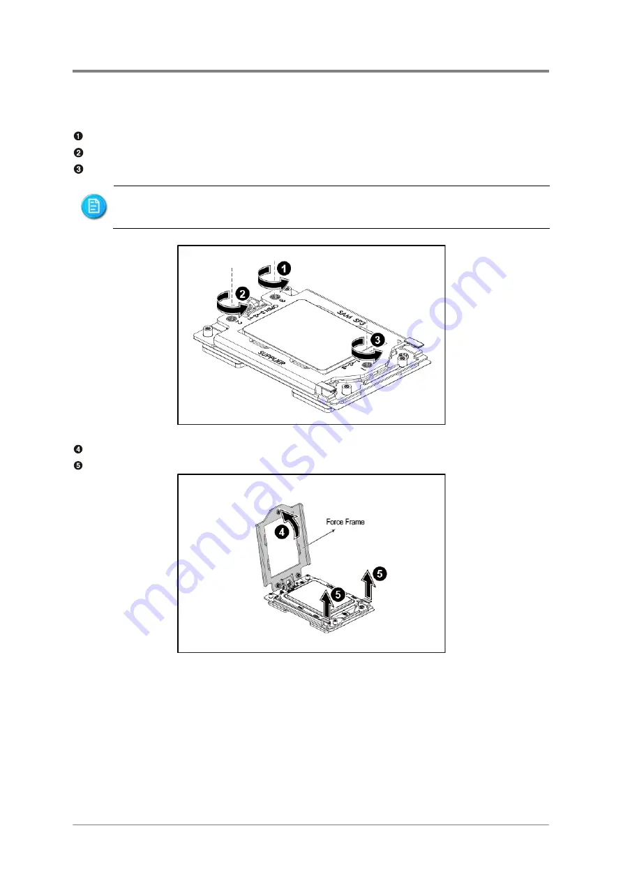
To remove the processor
Remove the screw marked with “3” around it.
Remove the screw marked with “2” around it.
Remove the screw marked with “1” around it.
Figure 2-3 Releaing the Force Frame
Open the force frame.
Hold the two clips of the rail frame and lift them up.
Figure 2-4 Opening the Force Frame
To release the force frame, you must remove the screws following the sequence of
“3”, “2” and “1” marked around them.
Summary of Contents for P47 series
Page 1: ...P N 2017 MNU 000016 June 2018 Revision A 2U Server System Service Manual P47 ...
Page 3: ......
Page 64: ...Backplane Connectors OCP Card Connectors Chapter 3 Connectors ...
Page 67: ...Chapter 4 Cable Routing ...
Page 68: ...Cable Routing 2017 MNU 000016 4 1 4 Cable Routing ...
Page 69: ...China RoHS Regulations Taiwan BSMI Electromagnetic Emissions Notices Appendix 1 ...
Page 71: ...Appendix 2017 MNU 000010 II Taiwan BSMI Figure II Taiwan BSMI ...
Page 75: ...Appendix 2 BIOS SPEC ...
Page 76: ...BIOS Setup User Manual K800QG4 rev 0 01 Mar 2018 ...
Page 100: ...Appendix 3 BMC SPEC ...
Page 101: ...K800G4 BMC Specification 1 K800G4 BMC Specification June 22th 2018 ...


