The function of the iV-Light ventilation system requires the simultaneous operation of two
iV-Light ventilation units in push-pull mode. This section therefore describes the connection of a
pair of units, not a single unit.
26
INSTALLATION AND ASSEMBLY
26
iV-Light ventilation unit | Installation instructions
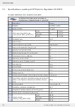
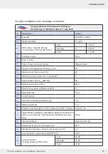
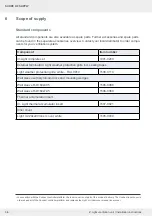
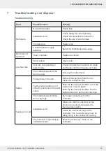
4.7 Electrical connection of the reversible fan
NOTICE
Incorrect electrical connection will
damage the fan motor.
• Always connect the ventilation unit to the mains supply via a controller.
• Ensure the correct sequence of the wire colours so that the fans start.
Stripping tool, screwdriver, blade, wire end ferrules (3 x 0.75 mm²)
Requirements:
• The reversible fan is inserted into the wall sleeve.
►
Shorten the controller connecting cable, 3-wire, to
your determined wall thickness minus 200 mm.
►
Remove the cable sheath from the controller
connecting cable.
NOTICE: Using the wrong wire end
ferrules to connect the cables in the plug-
in connector
will lead to a short circuit in the
fan BUS!
• Use wire ferrules with collars to connect
the wire strands.
►
Press wire end ferrules onto the cables, cable
cross-section 0.75 mm².
►
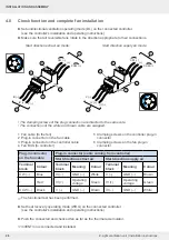
Loosen the plug connections on the
reversible fans of the two ventilation units.
►
Align the plug connectors on the ventilation units so
that the clamping screws on both are facing in the
same direction (e.g. upwards).
3 x 0.75 mm²
Summary of Contents for 1001-0200
Page 1: ...www inventer de Installation instructions iV Light ...
Page 37: ...37 WARRANTY AND GUARANTEE 37 iV Light ventilation unit Installation instructions NOTES ...
Page 38: ...38 WARRANTY AND GUARANTEE 38 iV Light ventilation unit Installation instructions NOTES ...
Page 39: ...39 WARRANTY AND GUARANTEE 39 iV Light ventilation unit Installation instructions NOTES ...


