9
SYSTEM OVERVIEW: IV-LIGHT VENTILATION UNIT
9
iV-Light ventilation unit | Installation instructions
2.1 Construction
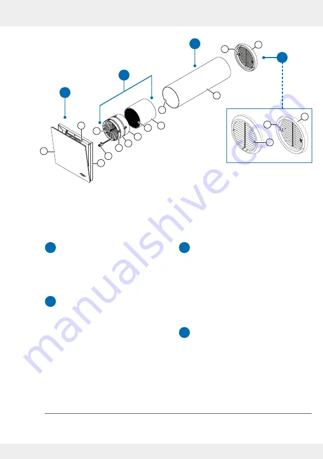
Figure 1: Overview of the iV-Light ventilation unit
Components
Thermal accumulator insert
(thermal accumulator and inVENTron)
Light inner cover
External termination:
Light weather protection grille
1)
Wall sleeve
1 Weather protection grille
2 Fixing claws (2 x, pre-installed)
3 Fixing screws (2 x, pre-installed)
1 R-D160 wall sleeve
2 Recess for controller connecting
cable
3 Thermal accumulator with insulation
4 Thermal accumulator handle
5 Standard guiding vane (wide)
6 Xenion reversible fan
7 Slim guiding vane (narrow)
8 Guiding vane knob
9 BUS plug connection
10 Inner cover base plate
(incl. ISO Coarse 60 % dust filter)
4 Inner cover panel
11 Connecting element
1)
The description of the components of all other possible external terminations can be found in the separate installation instructions
of the respective external termination.
A
B
D
C
A
B
C
D
1
3
5
8
11
6
2
9
1
2
7
10
12
13
14
15
4
Summary of Contents for 1001-0200
Page 1: ...www inventer de Installation instructions iV Light ...
Page 37: ...37 WARRANTY AND GUARANTEE 37 iV Light ventilation unit Installation instructions NOTES ...
Page 38: ...38 WARRANTY AND GUARANTEE 38 iV Light ventilation unit Installation instructions NOTES ...
Page 39: ...39 WARRANTY AND GUARANTEE 39 iV Light ventilation unit Installation instructions NOTES ...


