


21
INSTALLATION AND ASSEMBLY
21
iV-Light ventilation unit | Installation instructions
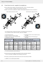
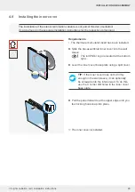
►
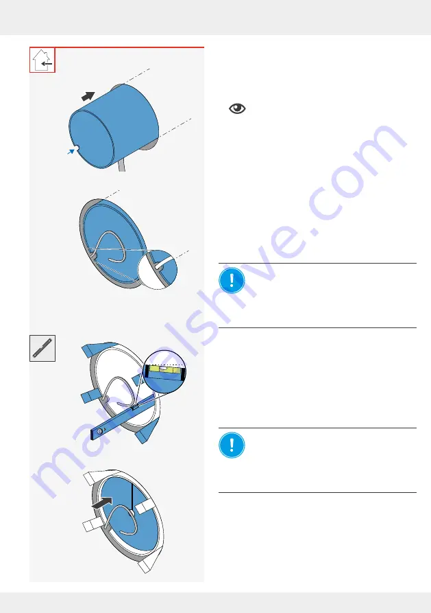
Remove the styrofoam discs from the wall sleeve.
►
Insert the wall sleeve into the wall opening so it is
flush with the interior wall.
Note the thickness of the plaster.
The recess for the connecting cables is
located on the interior wall side and near
the cables laid to the wall opening.
►
Guide all connecting cables through the cut-out in
the wall sleeve.
NOTICE: Accumulation ofcondensation
water in thewall sleeve.
Damage to exterior wall and masonry and the
building structure!
• Attach the wall sleeve with a slope of
1° to 2° to the exterior wall.
►
Attach the wall sleeve inside and outside with the
mounting wedges so that there is a slope of 1 – 2°
to the exterior wall.
►
Check the angle of the wall sleeve using a spirit
level.
NOTICE: Contamination of the wall sleeve
by e.g. plaster residues
leads to damage of
the components in the wall sleeve.
• Before foaming the free space between the
wall sleeve and masonry, insert styrofoam
discs.
►
Insert the styrofoam discs into the wall sleeve from
the inside and outside.
1 – 2°
!
Summary of Contents for 1001-0200
Page 1: ...www inventer de Installation instructions iV Light ...
Page 37: ...37 WARRANTY AND GUARANTEE 37 iV Light ventilation unit Installation instructions NOTES ...
Page 38: ...38 WARRANTY AND GUARANTEE 38 iV Light ventilation unit Installation instructions NOTES ...
Page 39: ...39 WARRANTY AND GUARANTEE 39 iV Light ventilation unit Installation instructions NOTES ...


