


27
INSTALLATION AND ASSEMBLY
27
iV-Light ventilation unit | Installation instructions
►
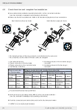
Reconnect the connected plug-in connector to the
plug-in connector on the reversible fan.
a Ventilation unit with start direction extract air mode
b Ventilation unit with start direction supply air mode
The reversible fan is connected to the controller.
In paired operation, one reversible fan starts in
extract air mode, the other in supply air mode.
This start direction is determined by the different
connection sequence of the three fan BUS cables
in the plug-in connector.
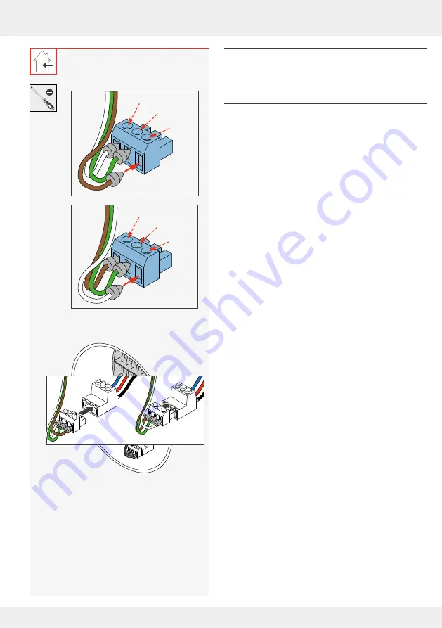
►
Secure the three fan BUS cables (controller
connecting cables) in the plug-in connector:
Exhaust air mode:
• (White) cable III (-) in the left pole.
• (Green) cable IV (+) in the middle pole.
• (Brown) cable V (-) in the right pole.
Supply air mode:
• (Brown) cable V (-) in the left pole.
• (Green) cable IV (+) in the middle pole.
• (White) cable III (-) in the right pole.
IV (+)
III (–)
V (–)
ETA
IV (+)
V (–)
III (–)
SUP
(Exhaust air)
(Supply air)
a
b
Summary of Contents for 1001-0200
Page 1: ...www inventer de Installation instructions iV Light ...
Page 37: ...37 WARRANTY AND GUARANTEE 37 iV Light ventilation unit Installation instructions NOTES ...
Page 38: ...38 WARRANTY AND GUARANTEE 38 iV Light ventilation unit Installation instructions NOTES ...
Page 39: ...39 WARRANTY AND GUARANTEE 39 iV Light ventilation unit Installation instructions NOTES ...


