background image

26

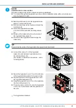
INSTALLATION AND ASSEMBLY

aV100 extract air system – Avio N 100 

 Installation and operating instructions

5.5 

Adjust length of wall sleeve

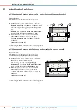
aV100 extract air system with weather protection hood (standard model)

Requirements: 

The interior and exterior walls are completed.

Ö

Ö

The length of the wall sleeve has been adjusted.

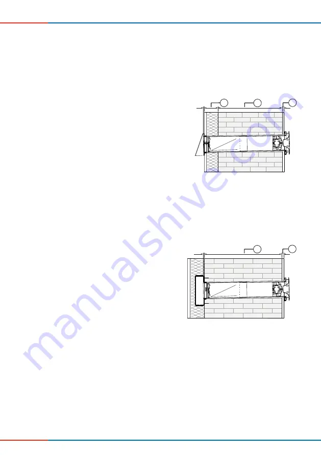
aV100 extract air system with flat duct and reveal grille (corner model)

Requirements: 

The interior and exterior walls are completed.

Ö

Ö

The length of the wall sleeve has been adjusted.


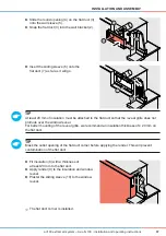
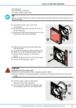
Determine the exact wall thi 5 mm.

Ensure to

 add the thickness of the render and 

insulation (1), masonry (2) and interior plaster 

(3).

Ensure that 

the sleeve of the wall sleeve has 

an overhang of 5mm on the exterior wall.


Slide the sleeve of the wall sleeve and the 

tube of the wall sleeve inside each other 

until the calculated wall thi5 mm is 

reached  

(see table on page 26).

3

2

1 - 2°

5

1


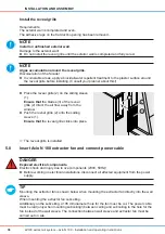
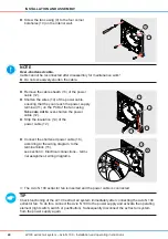
Determine the exact wall thi 10 mm.

Be sure to 

add the thickness of  

the masonry (1) and interior plaster (2).

Ensure that

 the sleeve of the wall sleeve has 

an overhang of 10 mm on the exterior wall.


Slide the sleeve of the wall sleeve and the 

tube of the wall sleeve inside each other 

until the calculated wall thi10 mm is 

reached  

(see table on page 26).

2

1

1 - 2°

10

Summary of Contents for av100

Page 1: ...av100 extract air system Avio N 100 Installation and operating instructions ...

Page 2: ...translation of the original German installation and operating instructions After completion of the installation it must be given to user tenant owner property management etc The contents of this documentation have been checked for compliance with the described hardware and software Nevertheless deviations may still occur therefore no guarantee of compliance can be provided This documentation is up...

Page 3: ...ng a plaster slot wall opening for the wall sleeve 21 5 3 Lay power cable 23 5 4 Install hygrostat optional 24 5 5 Adjust length of wall sleeve 26 5 6 Install the aV100 extract air system with weather protection hood standard model 28 5 7 Install the aV100 extract air system with flat duct and reveal grille corner model 32 5 8 Insert Avio N 100 extractor fan and connect power cable 38 5 9 Install ...

Page 4: ...l on the left side of the instruction A signal word above the text indicates the hazard level If several danger levels exist the highest level safety instruction is always used DANGER Type and origin of the hazard Imminent danger of serious personal injury Possible consequences of the hazard Measures to avoid the hazard Warning Type and origin of the hazard Possible danger of serious personal inju...

Page 5: ... the requirements of protection class II Do not lay the power cable while it is live Before installation if necessary perform a biocidal pretreatment water repellent treatment of the plaster surface around the weather protection hood reveal grille in order to prevent algae accumulation on the weather protection hood and a discolouration of the façade Consult your building planner about this Instal...

Page 6: ... be fitted to the outside wall for structural or other reasons e g listed buildings The connection of a hygrostat is available as an option The aV100 extract air system can be used in the following rooms Bathrooms toilets Utility rooms Kitchens Hallways Features Avio N 100 extractor fan with run on function Can be installed in protection area 1 bath and shower rooms to VDE 0100 Fan with low power ...

Page 7: ...r wall thickness less than 320 mm the tube and sleeve can be shortened by max 185 mm 1 3 4 2 5 9 8 6 7 10 1 Panel inner cover 2 Spacer 3 Inner cover base plate 4 Extractor fan casing 5 Tube of wall sleeve 6 Sleeve of wall sleeve 7 Weather protection hood base plate standard model 8 Weather protection hood cover standard model 9 Non return valve 10 Fan 11 Flat duct corner model 12 Reveal grille cor...

Page 8: ...sion is inserted into the wall sleeve and stuck together at the seam with durable waterproof fabric tape Figure 3 aV100 extract air system with wall sleeve extension Inner cover Figure 4 Inner cover 2 3 1 1 Spacer 2 Inner cover base plate 3 Panel inner cover 4 3 2 1 4 3 2 1 aV100 extract air system standard model aV100 extract air system corner model 1 Sleeve of wall sleeve with non return valve a...

Page 9: ... Power cable terminal 230 V 50 Hz 2 Fan 3 Power cable entry 4 Inner wall attachment points 5 Inner cover retaining screw 6 PCB 7 Potentiometer 1 2 3 4 5 4 1 Standard model end plate Weather protection hood aV100 Corner model end plate Flat duct with reveal grille 1 Weather protection hood base plate standard model flat duct corner model 2 Opening for wall sleeve 3 Wall mount 4 Weather protection h...

Page 10: ...ting current The Avio N 100 has a run on function Optionally a hygrostat can be connected to control the fan depending on the relative air humidity The run on time determines how long the fan continues to run after switch off With activation of the run on time switch off is via a control element the Avio N 100 continues to run until the end of the set run on time and then turns off automatically T...

Page 11: ...umidity falls below the set limit the run on is activated The extractor fan will run until the end of the run on time and then switch itself off automatically 2 3 Control elements Potentiometer The potentiometer is located on the PCB of the Avio N 100 extractor fan It is used to set the run on time within a range of 5 30 minutes The run on time is factory set at 15 minutes Figure 8 Integrated pote...

Page 12: ... cannot be installed Keep a minimum distance of 250 mm to components walls and furnishings in the interior space 3 1 Dimensions Designation Depth length mm Width mm Height mm Dia mm Wall openings Borehole for wall sleeve Wall thickness1 115 Borehole in subceiling2 Thickness of subceiling 105 Installation elements Wall sleeve R D103 107x330x550 RV Tube 280 103 Sleeve 300 107 Wall sleeve extension T...

Page 13: ... Dimensioned drawing of wall opening with flat duct corner model 1 Minimum distance from adjacent components 2 Note insulation thickness and possibly shutters 250 1 4 2 1 250 78 78 Ø115 3 1 Wall opening 2 Position of weather protection hood aV100 3 Bottom edge of reveal grille lintel 2 4 Door window frame 200 1 5 250 102 102 Ø115 3 4 1 2 1 Wall opening 2 Flat duct position 3 Bottom edge of reveal ...

Page 14: ...igure 11 Dimensioned drawing of wall sleeve aV100 Flat duct corner Figure 12 Dimensioned drawing of flat duct corner 300 50 280 Ø 103 Ø 107 5 1 1 4 2 3 500 1000 204 70 60 1 Ø107 2 1 Flat duct corner 2 Opening for wall sleeve 1 Tube of wall sleeve 2 Interior wall side 3 Exterior wall side 4 Fixing element 5 Sleeve of wall sleeve ...

Page 15: ...uctions Weather protection hood aV100 Figure 13 Dimensioned drawing of weather protection hood aV100 Reveal grille Figure 14 Dimensioned drawing of reveal grille 93 232 76 2 1 154 157 63 78 2 1 1 1 Weather protection hood base plate 2 Weather protection hood cover 1 Reveal grille 2 Flat duct sliding sleeve ...

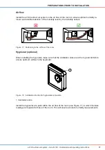
Page 16: ...extract air system or its components power source Electric shock and overheating due to short circuit 230V 50Hz Install aV100 extract air system outside electrical protection area 0 Install hygrostat outside electrical protection areas 0 to 2 Install light switch switch pushbutton outside electrical protection areas 0 to 2 Figure 16 Overview of electrical protection areas in bathrooms in accordanc...

Page 17: ...ty sensor Figure 17 Positioning in the air flow of the room Hygrostat optional When installing the hygrostat make sure that the ventilation slots are at the top and bottom to ensure optimum airflow to the hygrostat Figure 18 Installation direction for hygrostat vent position Install the hygrostat at a point within the air flow of the room see Figure 17 in which moisture readings correspond to thos...

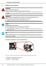
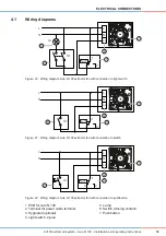
Page 18: ...0 extract air system outside protection areas 0 to 2 Note Insufficient wire cross section Excessive voltage drop and or contact cannot be guaranteed For the power cable use a wire cross section of 1 5 mm To connect the optional hygrostat use a 2 wire installation cable with a wire cross section of at least 0 75 mm TIP The aV100 extract air system can be combined with a light switch 2 pole or conne...

Page 19: ...tch Figure 21 Wiring diagram Avio N 100 extractor fan with connection to switch Figure 22 Wiring diagram Avio N 100 extractor fan with connection to pushbutton L N N L Ls La S1 rF 1 4 2 1 2 4 5 3 L N N L Ls S1 rF 1 4 2 1 2 6 3 L N N L Ls S1 rF 1 4 2 1 2 7 3 1 PCB for Avio N 100 2 Terminal for power cable terminal 3 Hygrostat optional 4 Light switch 2 pole 5 Lamp 6 Switch closing contact 7 Pushbutt...

Page 20: ...of water va pour from the living space into the wall This water vapour can condense to water at cold spots in the wall and thus lead to thermal bridges Rain barrier The rain barrier is waterproof and resists rainwater up to a certain pressure This barrier is lo cated on the outside and is permeable to water vapour in order to bring the moisture out of the wall and keep the wall sufficiently dry fo...

Page 21: ...lling masonry on building exterior Remove objects from the immediate vicinity of the building s exterior Tip Creating the wall opening for the wall sleeve is shown below when mounting the extractor fan into the wall sleeve on the exterior wall When mounting the extractor fan subceiling the wall opening for the wall sleeve must be created on the exterior wall between ceiling and subceiling Addition...

Page 22: ...at least 200 mm distance from bottom edge of the reveal lintel and interior adjacent components in order to install the inner cover and the reveal grille correctly Note the insulation thickness and possibly shutters With both models take care not to create the wall opening in the vicinity of radiators heaters and keep a minimum frontal clearance of 300 mm otherwise maintenance work cannot be carri...

Page 23: ...onnect all affected equipment from the power supply Observe the requirements for protection class II when laying the power cable Requirements The wall opening is ready The plaster or wall slot has been milled Ö Ö The power cable has been laid Connect the power cable to the switch push button see section 4 1 Electrical connections wiring diagrams Lay the power cable 3 wire 1 between the switch push...

Page 24: ...ion areas 0 to 2 TIP Position the hygrostat in the air flow of the room making sure that the humidity readings at the place of installation correspond to those of the room in order to obtain representative humidity measurements Requirements The installation location has been chosen Lay the 2 wire hygrostat cable between the control element and hygrostat installation loca tion see section 4 1 Elect...

Page 25: ...l plugs 4 Screw the hygrostat base plate 7 to the interior wall with mounting screws 8 Break out the cable entry 6 on the back of the hygrostat base plate 7 Run the 2 wire hygrostat cable through the cable entry 5 8 4 7 6 Connect the wires 11 of the hygrostat cable 10 with terminal 1 and terminal 4 on the terminal block 10 see section 4 Electrical connections termi nal assignment 9 10 11 4 1 Mount...

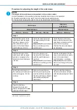
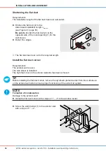
Page 26: ...ckness 5 mm Ensure to add the thickness of the render and insulation 1 masonry 2 and interior plaster 3 Ensure that the sleeve of the wall sleeve has an overhang of 5mm on the exterior wall Slide the sleeve of the wall sleeve and the tube of the wall sleeve inside each other until the calculated wall thickness 5 mm is reached see table on page 26 3 2 1 2 5 1 Determine the exact wall thickness 10 m...

Page 27: ...he tube of the wall sleeve into the sleeve of the wall sleeve extension with at least a 50 mm overlap Shorten the tube and sleeve as necessary Step 2 Shorten the tube of the wall sleeve with an angle grinder or a jigsaw to the determined wall thickness 40 mm From the interior pull the tube from the sleeve until the wall thickness is reached Ensure that the wall sleeve still has an overhang on the ...

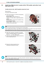
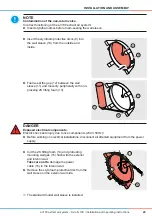
Page 28: ...wall Tip Do not remove the thread locks on the fixing elements until after completion of the wall work to prevent contamination of the threads Insert the wall sleeve 1 into the wall opening 3 from the outside Ensure that the fixing elements 2 and the non return valve 4 point towards the outside Ensure that the notch in the non return valve 4 is facing downwards Ensure that the wall sleeve has an o...

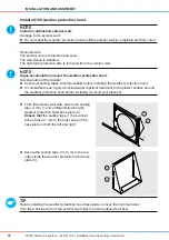
Page 29: ...tallations disconnect all affected equipment from the power supply Ö Ö The standard model wall sleeve is installed Insert the styrofoam protective discs 9 into the wall sleeve 10 from the outside and inside 9 10 Foam seal the gap 12 between the wall sleeve 11 and masonry peripherally with non pressing 2K fitting foam 13 11 13 12 Cut the 2K fitting foam 14 and protruding mounting wedges 15 flush wi...

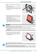
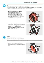
Page 30: ...sealing tapes circumferentially before installing the weather protection hood In vulnerable areas apply a biocidal water repellent treatment to the plaster surface around the weather protection hood before installing Consult your planner TIP Before installing the weather protection hood base plate remove the styrofoam disc from the wall sleeve from the exterior wall side to ensure adequate air flo...

Page 31: ...nstallation and Assem bly insert Avio N 100 extractor fan and connect power cable Remove the protective disc on the exterior wall side Turn the 2 screws 7 from the fixing elements 5 of the wall sleeve Screw the weather protection hood base plate 6 to the wall sleeve s fixing elements 5 with 2 screws 7 6 5 7 Place the weather protection hood cover 8 onto the weather protection hood base plate 9 fro...

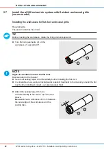
Page 32: ... upwards NOTE Algae accumulation around the flat duct Discolouration of the facade Secure all sealing tapes circumferentially before installing the flat duct In vulnerable areas apply a biocidal water repellent treatment to the masonry around the flat duct before installing Consult your planner about this Turn the fixing elements 2 on the wall sleeve 1 upwards 90 1 2 Attach the sealing tape 9 mm 4...

Page 33: ...styrofoam protective discs before foam sealing the wall sleeve Insert the styrofoam protective discs 12 into the wall sleeve 11 from the outside and inside 11 12 Attach the wall sleeve 10 inside and outside with the mounting wedges 9 so that there is a slope of 1 2 to the exterior wall Check the angle of the wall sleeve from the interior using a spirit level 1 2 9 10 Insert the wall sleeve 5 into ...

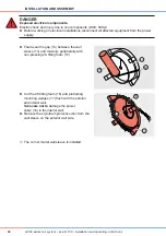
Page 34: ...fected equipment from the power supply Ö Ö The corner model wall sleeve is installed Cut the 2K fitting foam 16 and protruding mounting wedges 17 flush with the exterior and interior wall Take care not to damage the power cable 18 in the interior wall Remove the styrofoam protective disc from the wall sleeve on the exterior wall side 16 17 18 Foam seal the gap 14 between the wall sleeve 13 and mas...

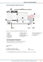
Page 35: ...ween 450 mm and 950 mm 3 Insulation thickness on the flat duct must be at least 20 mm Requirements None Add the dimensions y and z y z Add 35 mm to the calculated sum y z 35 mm Ö Ö The installation length of the flat duct is calculated Linstallation y z 35 mm 6 2 1 3 4 y 250 z 7 8 9 10 11 12 35 70 60 5 10 1 Masonry 2 Plaster 3 Inner cover 4 Wall sleeve 5 Wall mount 6 Window casement 7 Window frame...

Page 36: ...moved TIP Before installing the flat duct corner remove the styrofoam protective disc from the wall sleeve on the exterior wall side to ensure proper functioning of the extract air system Note Formation of condensation Damage to the exterior wall Install the flat duct corner with a slope of 1 2 to the window reveal Shorten the flat duct 2 to the determined installation length Linsertion see Figure...

Page 37: ...ct Tip Mask the outlet opening of the flat duct corner before applying the render This will prevent contamination of the flat duct Ö Ö The flat duct corner is installed Slide the round opening 4 on the flat duct 3 onto the wall sleeve 5 Snap the flat duct 3 into the wall bracket 2 3 2 5 4 Insert the sliding sleeve 6 onto the flat duct 7 as far as it will go 7 6 Fit insulation 8 with a thickness of...

Page 38: ...and connect power cable DANGER Exposed electrical components Electric shock and injury due to live components 230V 50Hz Before working on electrical installations disconnect all affected equipment from the power supply Tip Mounting the extractor fan is shown below when mounting the extractor fan directly into the wall sleeve When mounting the extractor fan subceiling Additionaly on the subceiling ...

Page 39: ...uipment from the power supply Unscrew the inner cover 2 from the fan casing 1 Remove the inner cover 2 from the front of the fan casing 1 Remove the styrofoam protective disc from the wall sleeve on the interior wall side 1 2 Insert the power cable 5 through the borehole in the 7 fan casing 8 From the interior slide the fan casing 8 into the wall sleeve 6 as far as the interior wall 5 7 8 6 Place ...

Page 40: ...activate the operating element light switch switch or pushbutton Subsequently disconnect the extract air system from the power supply again Connect the shortened power cable 16 according to the wiring diagram to the terminal block 15 see section 4 Electrical connections termi nal assignment wiring diagrams 15 16 Ls L N Remove the cable sheath 13 of the power cable 12 Shorten the wires 14 of the po...

Page 41: ...g the top edge of the inner cover base plate red arrow 2 in the upper strip green arrow of the fan casing 1 Press the inner cover base plate 2 onto the fan casing 1 at all four corners Ensure that the inner cover base plate 2 clicks into place 2 1 Screw the inner cover base plate 4 to the bottom edge of the fan casing 3 4 3 Place the panel inner cover 5 on the right side of the spacer 8 of the inn...

Page 42: ...and injury due to live components 230V 50Hz Before working on electrical installations disconnect all affected equipment from the power supply Ö Ö The inner cover has been disassembled Slide the inner panel cover 1 to the right until it audibly disengages Remove the inner panel cover 1 from the front 1 Undo the screw 3 on the bottom edge of the inner cover base plate 2 2 3 Gently pull on the botto...

Page 43: ...ments The aV100 extract air system is connected to mains voltage Ö Ö The aV100 extract air system was operated via a switch Turn the room lighting on via the light switch 1 blue dot Ö Ö The aV100 extract air system is switched on Turn the room lighting off via the light switch 1 red dot Ö Ö The run on time is activated Ö Ö The extract air system will run until the end of the run on time and then s...

Page 44: ...a switch pushbut ton and the fan switching off can be freely set within a range of 5 minutes to 30 minutes The potentiometer for setting the run on time is located on the PCB of the Avio N 100 extractor fan The run on time is factory set at 15 minutes Increase the run on time Requirements The ventilation system is disconnected from the power circuit The inner cover is removed see section 5 10 Ö Ö ...

Page 45: ...r system is switched on Ö Ö The hygrostat is set Turn the adjuster 1 on the potentiometer 2 anti clockwise with a screwdriver 5 Min 30 Min 2 2 1 Turn the rotary control 1 clockwise until the desired value is above the marking arrow 2 Ö Ö The relative humidity limit at which the extractor fan is activated has been raised Turn the rotary control 1 anti clockwise until the desired value is above the ...

Page 46: ...m aggressive gases dust and oils Air flow characteristic of Avio N 100 extractor fan Figure 24 Air flow performance of Avio N 100 extractor fan Extractor fan with run on function Avio N 100 Feature Value Protection class II Type of protection IP44 Input voltage AC 230 V 50 Hz Power consumption 6 4 W Width x Height x Depth 159 x 159 x 115 Weight 590 g Noise emission rated 28 dB A Run on time 5 minu...

Page 47: ...nger 1 pole NO or NC Ambient temperature 40 C 60 C Working temperature 0 C 60 C Width x Height x Depth 81 mm x 81 mm x 28 mm Weight Approx 60 g Wall sleeve Components Length depth mm Dimensions mm Weight g Sleeve of wall sleeve 300 Ø 107 270 with pre installed non return valve Tube of wall sleeve 280 Ø 103 180 Wall sleeve extension Identical to the wall sleeve without non return valve and fixing e...

Page 48: ...ight g Weather protection hood aV1001 46 154 x 157 424 1 available in white RAL 9016 grey RAL 9006 and iron grey RAL 7011 Inner cover Designation Length depth mm Dimensions W x H in mm Weight g Inner cover Avio N 100 white RAL 9010 115 159 x 159 135 Reveal grille with sliding sleeve Designation Length depth mm Dimensions W x H in mm Weight g Reveal grille 76 93 x 232 153 ...

Page 49: ...nts Order number aV100 extract air system 1001 0140 Installation and operating instructions 7002 0064 Avio N 100 extractor fan with run on function and inner cover Components Order number Avio N 100 3002 0265 Wall sleeve Components Order number Wall sleeve R D103 107x330x550 RV 1506 0079 Weather protection hood aV100 Components Order number Weather protection hood aV100 white RAL9016 1508 0043 Wea...

Page 50: ...s and spare parts Accessories Components Order number Wall sleeve extension aV 2 piece 1002 0021 Self adhesive fabric tape 50 m x 48 mm 1004 0051 Hygrostat 1002 0015 2K fitting foam for companies only 1004 0050 Spare parts Components Order number Grille for duct 60x204 2001 0070 Cover IB Avio V 159x159 RAL9003 3006 0240 ...

Page 51: ...d soda acids or chlorine Detergents A commercially available detergent in warm water can be used for cleaning The following tools may be used for cleaning lint free soft cloth soft brush Recommended maintenance schedule The listed maintenance activities and intervals are recommendations of the inVENTer GmbH As required your personal maintenance schedule may deviate Interval Assembly Maintenance ac...

Page 52: ...from the fan Clean the extract air system Fan blades contaminated Clean fan blades Disposal Dispose of the product in compliance with the applicable national regulations The products described in these installation and operating instructions are largely recyclable due to their low pollutant processing Contact an electronic appliance disposal company to ar range environmentally friendly recycling a...

Page 53: ...e aV100 extract air system damage is caused by force majeure or environmental influences damage occurs due to the chemical and or electrochemical action of liquids or gases Claims Check the delivery for completeness and transport damages upon receipt using the delivery note Report missing items within four weeks Documentation This documentation describes the functionality of the standard scope The...

Page 54: ...54 WARRANTY AND SERVICE aV100 extract air system Avio N 100 Installation and operating instructions Notes NOTES ...

Page 55: ...55 WARRANTY AND SERVICE aV100 extract air system Avio N 100 Installation and operating instructions Notes NOTES ...

Page 56: ...56 WARRANTY AND SERVICE aV100 extract air system Avio N 100 Installation and operating instructions Notes NOTES ...

Page 57: ...phone 49 0 36427 211 0 Fax 49 0 36427 211 113 E Mail info inventer de Website www inventer de Managing Director Annett Wettig VAT ID number DE 815494982 Jena District Court HRB 510380 Picture credits inVENTer GmbH 2015 All rights reserved inVENTer GmbH 2015 Subject to modifications All information is supplied without guarantee No liability is accepted for printing errors COMPANY DETAILS ...

Page 58: ...ENTer GmbH Ortsstraße 4a D 07751 Löberschütz Telephone 49 0 36427 211 0 Fax 49 0 36427 211 113 E Mail info inventer de Version 11 2015 Subject to technical changes Order number 7002 0065 inVENTer GmbH 2015 ...

Reviews: