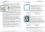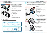
NOTE:
Only lay and connect the fan-BUS (controller cable) in a voltage-free state. Disconnect
the controller's power supply when connecting the cable to the control unit (sMove operating unit
or Clust-Air module CAM17).
For information containing the routing and connection of the fan-BUS (e. g. maximum cable
length) see the repective controller's installation and operating instructions.
Requirement:
The wall opening is created.
18
19
INSTALLATION AND ASSEMBLY
INSTALLATION AND ASSEMBLY
iV-Compact ventilation system
•
Installation and operating instructions
iV-Compact ventilation system
•
Installation and operating instructions
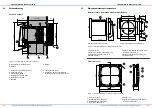
Using the Simplex wall build-in system
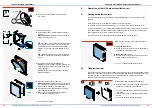
Requirement:
Das Bauvorhaben befindet sich in der Rohbauphase.
►
Insert the Simplex wall build-in system into the
appropriate place in the masonry.
Observe
the designations (red arrow) for installati-
on inside/outside the wall sleeve: The slope inside
the wall sleeve leads towards the exterior to ensu-
re the drain of emerging condensate. Observe the
minimum distances.
►
Wall in the Simplex wall build-in system.
►
Fit insulation and apply inner plaster as well as
exterior render.
4.3
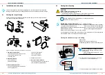
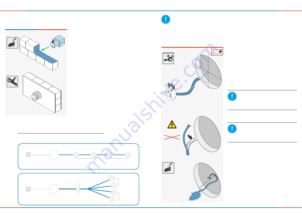
Laying the fan-BUS
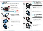
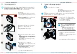
In series:
►
Cut the wall sleeve with an overhang of Y= 45 mm
on the exterior wall side.
►
Lay the fan-BUS (
4.3).
►
Proceed with fitting the weather protection hood
(
4.5).
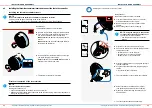
Star shaped:
Ö
The Simplex wall build-in system is fitted.
►
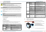
Lay the controller cable, three-wire (braided flex)
from the control unit to the wall opening for the
ventilation unit.
>M
in.
X
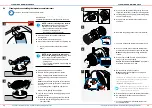
►
Fill the plaster/wall channel.
Make sure
that the cable end protrudes approx.
500 mm into the interior
NOTE:
Laying cables whose sheath is
not resistant to plastering under plaster
leads to a short circuit and cable fire!
• Lay cables inside an empty conduit if
necessary.
Ö
The fan-BUS (controller cable) is laid.
►
Create the plaster/wall channel between the cont-
rol unit and wall opening.
Make sure that th
e plaster/wall channel for the
controller cable is at an angle of 45° to the bottom
left.
►
Close off the wall sleeve inside and out until the
wall sleeve is inserted.
Ö
The plaster/wall channel for the cable (fan-
BUS) is created.
NOTE:
The use of a too small cable
cross-section
results in a too high voltage
drop and/or contacting is not guaranteed!
• Use a cable
cross-section of at least
0.75 mm²
for the fan-BUS.
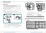
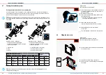
Wiring scheamtich sketches:
Y
0°
Y
0°
45°
CAM17
(MZ-Home)
sMove
6 – 16 V DC
230 V AC
Switching
PSU
Control unit
Connecting
terminals
Ventilation units
Ventilation
unit
Operated in pairs
Operated in pairs
Operated in
pairs
Cable: Strands, 3-wire, length see
controller
Cable: Strands, 3-wire, max. length 33 m
Switching
PSU
Control unit
Operated in
pairs


