26
27
INSTALLATION AND ASSEMBLY
INSTALLATION AND ASSEMBLY
iV-Compact ventilation system
•
Installation and operating instructions
iV-Compact ventilation system
•
Installation and operating instructions
4.7
Starting the ventilation systemn
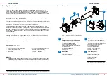
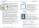
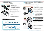
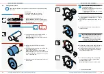
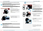
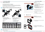
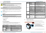
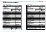
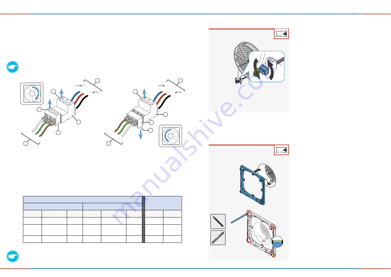
Setting the start direction of the reversing fan
In paired operation, one reversing fan is set in exhaust air direction, the other reversing fan is
set to supplyair direction. After the function test, the socket of the plug-in connection on the fan,
which is to start in supply air operation in pairs, must be turned.
TIP:
Note the starting direction of the respective unit in the connection plan. (Appendix 1) Thus
the starting direction is determined for upcoming maintenance tasks and a wrong connection will
be avoided.
Starting direction – Extract air:
•
The locking screws of the plug-in
connection's plug and socket are pointing
to the same direction.
Starting direction – Supply air:
•
The locking screws of the plug-in
connection's plug and socket are pointing
to different directions.
1 Wire's to fan
2 Plug
3 Socket
4 Fan-BUS (wires to controller)
5 Locking screws on socket
6 Locking screws on plug
Plug (Cable from controller)
Socket
(Cable from fan)
Starting direction: Extract air
Starting direction: Supply air
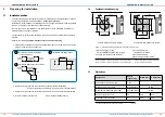
Terminal
Signification
Colour Terminal
Signification
Colour
Terminal Colour
III (–)
GND (–)
White
V (–)
GND (–)
Brown
CW (–)
Blue
IV (+)
Operating
voltage
Green
IV (+)
Operating
voltage
Green
+
Red
V (–)
GND (–)
Brown
III (–)
GND (–)
White
CCW (–) Black
TIP:
When looking from the side, the plug-in connection forms an
"S"
like
"Supply"
when in
starting direction Supply air.
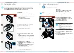
Requirement:
The functional test is performed.
►
Disconnect the plug of the ventilation unit which is
to operate in supply air mode from the socket of
each pair of fans.
►
Rotate the socket by 180°.
►
Plug in the socket with the locking screws to the
opposite side again.
Ö
The plug-in connections locking screws are
pointing to opposite directions.
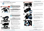
►
Slide inVENTron as far as the thermal
accumulator.
►
Select heat recovery mode (HR).
(see operating instructions for the controller).
Ö
The reversible fan is connected to the controller.
4.8
Fitting the inner cover
Requirement:
The thermal accumulator is inserted.
The fan's starting direction has been set.
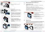
►
Align the base plate using a spirit level.
►
Mark out the four corner drillings for fastening the
base plate.
►
Place the base plate centrically to the wall sleeve
on the interior wall.
IV (+)
(+)
V (–)
III (–)
III (–)
V (–)
IV (+)
CW (–)
CCW (–)
(+)
CW (–)
CCW (–)
3
1
4
6
1
4
5
6
3
2
2
5


