background image

4

5

USER AND SAFETY INSTRUCTIONS

USER AND SAFETY INSTRUCTIONS

iV-Compact ventilation system 

 Installation and operating instructions

iV-Compact ventilation system 

 Installation and operating instructions

User and safety instructions

Thank you for purchasing this high quality product from inVENTer!

This section provides an overview of the basic safety precautions for safe and proper operation 

of your ventilation unit.

1.1 

User information

Concept of safety instructions

The safety and warning instructions in these operating instructions have a uniform structure 

and are marked with a symbol on the left side of the instruction. A signal word in front of the text 

also indicates the hazard level. If several hazard levels exist, the highest level safety instruction 

is always used.

The safety and warning instructions contain the following information.

SIGNAL WORD:


Type and origin of the hazard. 

Possible consequences of the hazard!

  Measures to avoid the hazard.

A signal word indicates the severity of the potential hazard unless the preventative measures 

are taken.

WARNING

 indicates possible danger of serious injury or death.

CAUTION


indicates possible danger of minor/significant injury.

NOTE

 indicates: Imminent or possible damage to property due to an adverse event/state.

If you see this sign, ensure you observe the described measures to prevent possible hazards 

and/or damage.

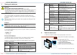
Other symbols and notices used in this documentation

In addition to the safety instructions, the following symbols are used:

TIP 

symbol indicates practical and useful tips for handling the ventilation unit.

tool symbol

 before an installation sequence lists any additional tools and materials 

required for the described task.
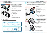
Red frame 

surrounding: Graphic shows the interior wall.

Blue frame

 surrounding: Graphic shows the exterior wall.

  ► 

Action required:

 this requires the user to perform a specific action.

 


Check the results:

 this requires you to check the results of the action you have performed.

1.2 

Safety instructions

These installation and operation instructions are part of the ventilation unit and must be per-

manently available. When handing the equipment/system to a third party, the installation and 

operation instructions must be handed over also. Before performing any work on the system, 

read the installation and operation instructions carefully and observe all information regarding 

installation, assembly, operation, cleaning and maintenance contained in this section. Also note 

the safety instructions that precede the described handling instructions. Non-observance of 

safety warnings could result in injury and/or property damage.

Intended use

The inVENTer ventilation units with heat recovery are used to ventilate living rooms and living 

spaces. They are controlled by a control unit of the inVENTer system.

General instructions

•  When installing the unit/system, observe the applicable standards, regulations and directi-

ves. In particular, the applicable building regulations, fire protection regulations and accident 

prevention regulations of the employers' liability insurance association.

•  Use the unit/system only in accordance with the applications described in this documentation 

and in the detailed installation and operating instructions and only in conjunction with the 

components recommended, approved and named in this documentation by inVENTer GmbH.

• 

Modifications or alterations to the unit/system are not permitted.

•  Your ventilation system has been developed exclusively for use in ambient temperatures 

within -20 – 50 °C.

•  Proper and safe operation of the unit/system requires proper transport, storage and installati-

on as well as careful usage and cleaning/maintenance.

Installation and assembly

• 

CAUTION: The system may only be installed by qualified personnel.

•  Before starting the work, you should have a project plan which shows the number of ventilati-

on units, the position of the ventilation units, the ventilation principle (cross ventilation, single 

room ventilation, exhaust ventilation) and the corresponding controllers. The exact positioning 

of the individual ventilation units and control units must be checked by the customer and, 

if necessary, adapted to the local conditions with the involvement of the responsible cons-

truction manager or the user. For optimum functionality, it is recommended that the unit be 

installed at an appropriate location in the upper wall area.

•  WARNING:

 For joint operation with room air-dependent and room air-independent fireplaces, 

safety measures must be taken to prevent the creation of a negative pressure in the building. 

The responsible chimney sweep and/or construction manager decides which measures are to 

be taken.

•  NOTE:

 The ventilation unit is not suitable for drying out buildings. Do not put it into operation 

until the construction work has been completed.

•  NOTE:

 Do not install the unit in the vicinity of room air thermostats or in the immediate en-

vironment/above sensitive pictures or furniture.

•  NOTE:

 Observe the specified minimum distances on both sides of the wall and frontally to 

avoid unintentional mixing of outside and exhaust air and to ensure access to the unit and its 

components.

•  NOTE:

 The wall mounting sleeve must be integrated into the building envelope (air resistance 

layer) in such a way that it is open to diffusion on the outside and impermeable to diffusion on 

the inside, taking account of structural specifications. Material for this must be provided by the 

customer. After installing the wall installation sleeve, bring the wall structure back up to the 

Summary of Contents for iV-Compact

Page 1: ...iV Compact Installation and operating instructions ...

Page 2: ...cessories and spare parts 41 10 Troubleshooting and disposal 42 11 Guarantee and warranty 44 12 Service 44 13 Appendix 1 Wiring protocol 45 14 Appendix 2 Cleaning protocol 46 INHALTSVERZEICHNIS Trademarks copyrights and property rights inVENTer Xenion inVENTron and Clust Air are registered trade marks of inVENTer GmbH The copyright of this document remains with the manufacturer Rights to all conte...

Page 3: ...ation units with heat recovery are used to ventilate living rooms and living spaces They are controlled by a control unit of the inVENTer system General instructions When installing the unit system observe the applicable standards regulations and directi ves In particular the applicable building regulations fire protection regulations and accident prevention regulations of the employers liability ...

Page 4: ...eaning and maintenance CAUTION Operation and or maintenance of the ventilation unit and its controllers must not be carried out by children and or persons who are not fully capable of doing so due to their physical sensory or mental capabilities inexperience or lack of knowledge Young children should be supervised to ensure that they do not play with the unit NOTE Your ventilation unit has scratch...

Page 5: ...ordering a wall sleeve with a length of 285 mm or 495 mm Both versions can be trimmed on site It is controlled via one of the following inVENTer system controllers1 sMove s4 sMove s8 MZ Home Components see fig page 9 Inner cover incl dust filter of class G4 Thermal accumulator insert thermal accumulator and inVENTron Wall sleeve Exterior closure Pollen and activated carbon filter op tions availabl...

Page 6: ...e season independent For special require ments pollen and activated carbon filters are available as an option A decentralised ventilation system is based on the free movement of air between individual pairs of ventilation units Therefore internal doors must not have air tight seals Ensure adequate air transfer measures An air gap of about 10 mm below the door unscrew the hinges by 5 mm use a venti...

Page 7: ... spray is possible Observe the following minimum distances for the unit s wall opening 1 between two ventilation units in push pull operation pair in the same room to avoid the mixing of outdoor air and exhaust air Horizontal or vertical installation Installation with height offset on the same wall Installation diagonally over corners 2 to adjacent components on the exterior wall observe insulatio...

Page 8: ...Protective hood cover 6 Brackets 7 Thermal accumulator 8 inVENTron Xenion reversible fan embedded in two Slim guiding vanes A Inner plaster internal structure B Masonry C Render 1 Upper drip rail 2 Bracket for thermal accumulator 3 x 3 Fastening screws for cover 4 x 4 Bottom drip rail 5 Exterior wall attachment with Ø 8 mm min 50 mm deep 4 x 6 Guidance for fastening screws 4 x 7 Protective grid Fl...

Page 9: ...njury and or material losses Provide protection against falling masonry on the outside of the building Remove objects from immediate vicinity of the building s exterior Drilling machine with core drill attachment or milling drill Ø 180 mm wall slot cutter hammer chissel Positioning of the wall sleeve 3 1 Installation position Minimum distance to adjacent components on exterior wall Observe insulat...

Page 10: ...xterior wall side Lay the fan BUS 4 3 Proceed with fitting the weather protection hood 4 5 Star shaped Ö Ö The Simplex wall build in system is fitted Lay the controller cable three wire braided flex from the control unit to the wall opening for the ventilation unit M in X Fill the plaster wall channel Make sure that the cable end protrudes approx 500 mm into the interior NOTE Laying cables whose s...

Page 11: ...ing foam cutter Requirements The wall opening Ø 180 mm is finished The fan BUS controller cable is in place Y 45 mm X A B C D NOTE Accumulation of condensate inside the wall sleeve Damage to the exterior wall and masonry as well as the building fabric Fix wall sleeve with a slope of 1 2 to the exterior wall Fix the wall sleeve in place inside and outside with mounting wedges to create a slope of 1...

Page 12: ... spirit level Mark out the four bore holes for fastening the base plate NOTE Damage to the masonry external wall due to misaligned drip rails Make sure that the slopes on both drip rails are aligned to down facing Ö Ö The weather protection hood is installed Drill the four holes with Ø 8 mm to a depth of min 50 mm Insert the wall plugs into the drill holes Secure weather protection hood base plate...

Page 13: ...m the packaging Requirement The weather protection hood is installed Remove the protective discs from the wall sleeve From the interior slide the thermal accumulator into the wall sleeve as far as the end stop Make sure that the handle is facing towards the interior Make sure that the controller cable fan BUS is facing towards the interior Trim the controller cable 3 wire to your deter mined wall ...

Page 14: ...ws on plug Plug Cable from controller Socket Cable from fan Starting direction Extract air Starting direction Supply air Terminal Signification Colour Terminal Signification Colour Terminal Colour III GND White V GND Brown CW Blue IV Operating voltage Green IV Operating voltage Green Red V GND Brown III GND White CCW Black TIP When looking from the side the plug in connection forms an S like Suppl...

Page 15: ... Opening closing the inner cover For correct functioning of your ventilation system the ventilation unit s inner cover must be opened Close the inner cover if you take the ventilation unit out of operation This will prevent an undesired air exchange i e an inflow of cold air into the living room In particular situations i e accidents with smoke or leaking gases it is necessary to close all doors a...

Page 16: ...nal maintenance plan may deviate from these recommendations Interval Assembly Maintenance activity Cleaning from the interior room Monthly Pollen filter Replace the contaminated pollen filter Inner cover Clean the surface of the panel with a damp cloth Quarterly Dust filter Wash the dust filter with warm water and detergent Or Replace defective dust filters Interval Assembly Maintenance activity H...

Page 17: ...logo is located on the bottom right Press the side detent lugs inwards on the inner cover base plate s spacers Slide the inner cover panel onto the spacers Ö Ö All spacers noticeably snap in Ö Ö You have cleaned changed the dust filter Clean the dust filter under warm running water Wait until the filter is completely dry or Dispose of the dust filter if defective 6 3 Removing the thermal accumulat...

Page 18: ...t you can reach both cables Ensure that the fan s side WITHOUT type plate is directed to the interior room side Place inVENTron on an even surface Remove the first guiding vane from the fan Step 1 Carefully bend the lateral strips on the guiding vane away from the fan one after the other Hold the first removed strip in the current position with one hand until the guiding vane is completely removed...

Page 19: ...tion class DIN EN 61140 III Type of protection DIN EN 60529 IP20 Filter class standard filter DIN EN 779 2012 G4 Air flow sensitivity at 20 Pa DIN EN 13141 8 S3 Frost protection Automatically due to push pull operation bis 20 C Weight g Max 3 850 Wall thickness incl plaster render mm 140 Wall opening mm Ø 180 Wall sleeve Ø 160 Conformity 7 2 Label according to EC Directive for energy related produ...

Page 20: ...de one direction devices only no s Internet www inventer de t Airflow sensitivity 29 3 u Indoor and outdoor air tightness m h n a v Annual electricity consumption kWh m a 0 76 w Annual heating saved kWh m a cold 83 39 average 42 63 warm 19 28 iV Compact manual control Product fiche iV Compact according to VO 1254 2014 EU dated 2014 07 11 Pt Description Data a Supplier s name inVENTer GmbH b Suppli...

Page 21: ... 223x223 white 1505 0036 inner cover Flair V 223x233 white incl sound insulation SDE 1505 0037 9 Accessories and spare parts Accessories Component Order number Dust filter G4 IC Flair V 233x233 2 x 1004 0175 Pollen filter IC Flair V 233x233 2 x 1004 0143 Carbon filter IC Flair V 233x233 2 x 1004 0158 Sound absorbing insert R D160 1004 0148 Sound protector SPR R D160 1004 0154 Wind protection inser...

Page 22: ...eeve as far as the joint tape Fan speed very high Set a lower output level on the controller Supply air is cold Installation error Make sure that the type plate on the Xenion fan is directed towards the heat accumulator Check the connector plug on the control ler The connector plug must be sitting firmly in the connector housing The controller is operating in continuous ventilation mode Select hea...

Page 23: ...her information about the warranty is available at www inventer eu warranty 12 Service Claims Check the delivery for completeness and transport damage upon receipt using the delivery note Report missing items immediately and at the latest within 14 days to your supplier distributor or factory representative Warranty and guarantee claims In the case of a warranty or guarantee claim contact your loc...

Page 24: ...pe Action A Inner cover Filter Inner cover Cleaning Filter Check clean or change if necessary depending on filter type Filter Check clean or change if necessary depending on filter type B Thermal accumulator Xenion reversible fan guiding vanes Wall sleeve Cleaning C Accessories Check clean or change if necessary COMPANY DETAILS PUBLISHER INVENTER GMBH ORTSSTRASSE 4A D 07751 LÖBERSCHÜTZ GERMANY TEL...

Page 25: ... inventer eu Version dated 04 2019 Subject to modifications Item number 5006 0005 inVENTer GmbH 2014 19 inVENTer GmbH Ortsstraße 4a D 07751 Löberschütz 49 0 36427 211 0 49 0 36427 211 113 info inventer de ...

Reviews: