

6
7
USER AND SAFETY INSTRUCTIONS
USER AND SAFETY INSTRUCTIONS
iV-Compact ventilation system
•
Installation and operating instructions
iV-Compact ventilation system
•
Installation and operating instructions
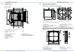
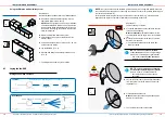
wall installation sleeve and observe the necessary barrier planes to avoid interruption of the
thermal insulation composite system. Consult your planner before installation!
• NOTE:
Install wall mounting sleeves and other air ducts with a gradient of 1 – 2° to the outer
wall to ensure drainage of any condensate.
• NOTE:
Do not install the ventilation system in places where direct contact with spray or splash
water is possible.
• NOTE:
To prevent algae from settling around the external closure, the installation instructions
must be observed exactly (attach all sealing strips!). We recommend a biocidal presetting/wa-
ter-repellent pre-treatment of the facade surface around the external finishes. Ask your planner
regarding this!
• NOTE:
To avoid damaging the walls, attach the inside and outside finish of the unit only to
completed and completely dried facades/walls.
• NOTE:
When installing components in (exterior) walls with insulation, use insulating plugs to
ensure that the components are securely fastened. Insulation plugs are not included in the
scope of delivery, they are available optionally!
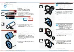
• NOTE:
The ventilation unit has scratch-sensitive plastic surfaces. In particular, do not touch
the inside panel with oily and/or dirty hands. Avoid contact with sharp or pointed objects such
as rings.
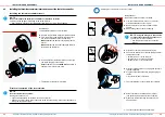
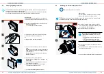
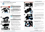
Wiring/ Connecting the reversing fan
•
CAUTION: The electrical connection of the system may only be carried out by qualified
personnel.
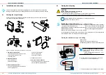
• CAUTION:
Lay and connect cables only in a voltage-free state (mains connection disconnec-
ted at all poles)!
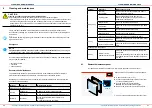
• NOTE
: Ventilation systems operated with safety extra-low voltage (SELV) have an operating
voltage of 6 – 16 V DC. They must not be connected directly to the 230 V mains, but must
always be connected and operated via a controller.
• NOTE:
Laying cables whose sheath is not resistant to plastering under plaster leads to a
short circuit and cable fire! Lay cables without a plaster-resistant cable sheath in the empty
conduit.
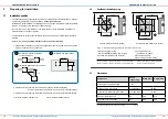
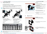
• NOTE:
The use of a too small cable cross-section leads to a too high voltage drop and/or
contacting is not guaranteed! For the fan BUS, use a cable cross-section of
at least 0.75 mm² (strand). Use ferrules with collars to connect the strands.
When using several ventilation units operated by several controllers, you must ensure that
the ventilation units are synchronized with each other. You should connect all controllers
via a mains fuse in the house distributor.
Operation, cleaning and maintenance
• CAUTION: Operation and/or maintenance of the ventilation unit and its controllers must
not be carried out by children and/or persons who are not fully capable of doing so due
to their physical, sensory or mental capabilities, inexperience or lack of knowledge.
Young children should be supervised to ensure that they do not play with the unit.
• NOTE:
Your ventilation unit has scratch-sensitive plastic surfaces. Do not touch the inner
cover with oily and/or dirty hands. Avoid contact with sharp or pointed objects, e.g. rings
• NOTE:
Do not use strong cleaning agents or solvents. Use a soft, damp cloth to clean the
plastic surfaces.
•
Never use the unit without the filters and inner cover.
• Use the sMove controllers exclusively to control inVENTer ventilation units with heat recovery
• Before performing cleaning or maintenance tasks, disconnect the controller's power supply
and put on gloves.
If your unit is defective, contact your local factory representative or our technical service.
Any improper use will result in the exclusion of any liability claims.
Unauthorized use
Any use which is not mentioned in the chapter "Intended use" shall be deemed to be improper
(unauthorized) use.
In particular, do not install/operate the device in areas where the following may occur:
• Environment containing a lot of oil or grease.
• Flammable, aggressive and corrosive gases, liquids or vapour.
• Extreme dust exposure.
• Ambient temperatures outside the range of -20 – 50 °C.
• Obstacles blocking access to or removal of components from the ventilation unit.
Qualified personnel
The unit/system may only be set up and operated in conjunction with this documentation, the
documentation of the individual components and the documentation for the controllers.
Installation, assembly and wiring
Assembly, electrical connection and initial commissioning of the device/system may only be
carried out by qualified personnel. Qualified personnel within the meaning of the safety instruc
-
tions in this documentation are persons who are authorized to assemble, commission and label
devices, systems and circuits in accordance with the standards of safety engineering.
Cleaning and maintenance
Any necessary cleaning or maintenance tasks can be carried out by the user by following the
instructions. Operation and/or maintenance of the ventilation unit and controller must not be
carried out by children and/or persons who are not fully capable of doing so due to their
physical, sensory or mental capabilities, inexperience or lack of knowledge.
Conformity
The ventilation unit complies with the technical safety requirements and standards for household
electrical appliances. It conforms to the applicable directives of the European Union:
• 2014/30/EC: Electromagnetic compatibility
• 2014/35/EC: Low voltage
• 2009/125/EC: Eco design
• 2011/65/EC: RoHS


