16
17
INSTALLATION AND ASSEMBLY
INSTALLATION AND ASSEMBLY
iV-Compact ventilation system
•
Installation and operating instructions
iV-Compact ventilation system
•
Installation and operating instructions
4
Installation and assembly
Lesen Sie das Kapitel vor dem Einbau sorgfältig durch, um Einbaufehler zu vermeiden. Die
Montage und der Anschluss des Lüftungssystems muss durch qualifiziertes Personal erfolgen.
4.1
Checking the scope of supply
Check the delivery for completeness and transport damage upon receipt using the delivery
note. Report missing items immediately.
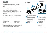
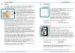
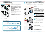
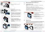
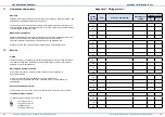
Figure 6: Standard components of ventilation unit iV-Compact
4x
4x
4x
4x
4x
1 Compact Protective hood
1 a: Fastening elements for exterior wall
1 b: Fastening screws for cover
1 c: Sealing tape
2 Wall sleeve R-D160
2 a: Protective discs
2 b: Mounting wedges
3 Thermal accumulator insert
3 a: Thermal accumulator with insulation
3 b: Slim guiding vane
3 c: Xenion reversible fan
3 d: Slim guiding vane
3 e: Plug-in connection
4 Installation instructions
5 Inner cover Flair V-233x233
4 a: Fastening elements for interior wall
4 b:
Dust filter G4 (preassembled)
4.2
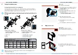
Creating the wall opening
CAUTION
Falling masonry while making wall opening.
Risk of injury and/or material losses!
• Provide protection against falling masonry on the outside of the building.
• Remove objects from immediate vicinity of the building's exterior.
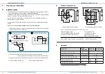
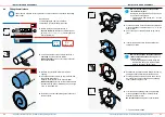
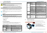
Drilling machine with core drill attachment or milling drill Ø 180 mm,
wall slot cutter, hammer, chissel
Positioning of the wall sleeve
3.1 – Installation position):
Minimum distance to adjacent components on exterior wall (Observe insulation thickness and any shutters):
•
Compact weather protection hood
250 mm from hole center circumferentially
Minimum distance to adjacent components on interior wall 250 mm from hole center circumferentially
Minimum distance to the front:
300 mm for cleaning and maintenance tasks
Make sure that the wall opening is not near any radiators.
In new buildings and for timber-frame construction, we recommend the use of the optional D180
wall installation block or the Simplex wall insallation system.
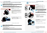
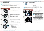
Creating the wall sleeve using a core drilling
Requirements:
Masonry must be dry and load-bearing.
No load-bearing elements in position of the planned hole.
►
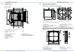
Drill a wall opening with a diameter of Ø 180 mm
at a slope of 1 – 2° to the exterior wall.
NOTE
:
Condenstae collecting in the wall
sleeve
leads to damage to the exterior wall
and masonry!
• Create wall opening at a slope of 1 – 2° to
the exterior wall.
1 – 2°
Ö
The wall opening for the ventilation unit is created.
Ø
180
2
5
2b
2a
4
5b
3
3a
3b
3e
3c
3d
1
1b
1a
1c
5a


