19
INSTALLATION AND ASSEMBLY
19
iV-Smart+ ventilation device | Installation instructions
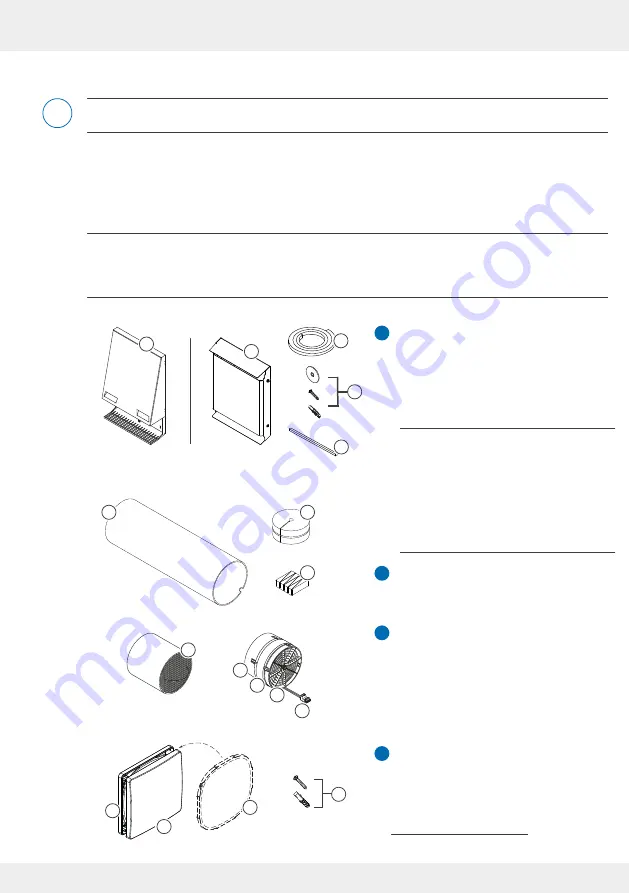
1 External termination
1 a: WSH Flex
1 b: WSH Smart
1 c: Sealing tape
1 d: Exterior wall fixing elements
1 e: End-stop tape
R-D160 wall sleeve
2 a: Styrofoam discs
2 b: Mounting wedges set
iV-Smart+ thermal accumulator insert
3 a: Insulated thermal accumulator
3 b: Standard guiding vane (45 mm)
3 c: Xenion reversible fan
3 d: Slim guiding vane (16 mm)
3 e: BUS plug connection
Flair inner cover
4 a: Inner cover base plate
4 b: Inner cover panel
4 c: ISO Coarse 60 % dust filter
4 d: Interior wall fixing material
4
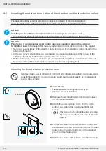
Installation and assembly
Read the section carefully before installation to avoid installation errors. The installation and
connection of the ventilation device must be carried out by qualified personnel.
4.1 Check the scope of supply
Check the delivery for completeness and transport damage upon receipt using the delivery note.
Report missing items immediately.
These assembly instructions describe the standard version of the product. For the scope of
delivery of the external termination variants, wall sleeves for integrating the Connect controller
platform, the Connect AP/UP and Undercover inner cover panels, please refer to the separately
available installation instructions for the respective system component.
The Smart and Flex weather protection
hoods are available in different colours,
the Flex weather protection hood addi-
tionally in different materials (stainless
steel / aluminium [with increased salt
resistance]) and must be ordered,
according to the desired colour and
texture.
WSH = Weather protection hood
4x
4x
4x
4x
4x
2
1a
1b
1d
2a
3a
3b
3c
3d
3e
4a
4b
1c
2b
1e
4d
4c
i
1
2
3
4


