41
inVENTer
®
iV12-Smart
®
/iV12-Smart
®
Corner ventilation system
•
Installation and operating instructions
TiP
Connect the ventilation unit initially in extract air mode (locking screws visible). This makes it
easier to test that the ventilation unit is working.
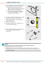
► Set exhaust air operation.
►
Connect plug (10) in to green socket (11) on
fan plug connector (12).
►
Ensure that the clamping screws on the
connector are facing upwards.
Ö
Ö
Exhaust air operation is set.
8
9
0
1
Ö
Ö
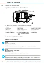
The thermal accumulator is assembled.
5.11
starting the ventilation system
TiP
One
fan must be connected in exhaust mode and another fan in supply mode in paired operation
(see section 4: Electrical connections). The functionality of the module and ventilation system
must be checked immediately following installation of the thermal accumulator and fan. The con-
troller should initially be set to ventilation mode during initial installation (start-up of the control-
ler).
Requirements
Thermal accumulator/fan are assembled.
Controller is set to performance level 0.
►
Check functionality of module/ventilation system.
►
Check freewheel function of the fan.
Ö
Ö
Fan is running freely.
►
Check connection of fan to controller.
Ö
Ö
Fan is connected.
►
Check voltage.
Ö
Ö
Voltage is present.
►
Set ventilation operating mode.
(See installation and operating instructions for the controller)
Ö
Ö
Ventilation operating mode is set.
assembly anD insTallaTion


