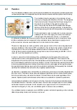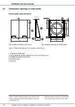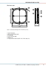
3 Reveal
4 Door/window frame
5 Bottom edge of lintel
4)
313
88
265
61
Ø
200
233
1 – 2°
Wall thickness ≥ 280
15
PREPARING FOR INSTALLATION
Ventilation device iV14-MaxAir
•
Installation and operating instructions
3.3
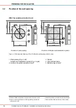
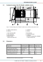
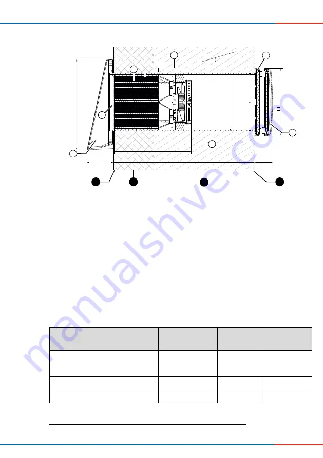
Sectional drawing of the iV14-MaxAir ventilation device
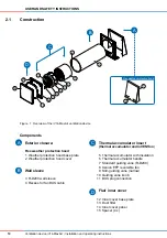
Figure 3: Sectional drawing of the iV14-MaxAir ventilation device with Flex weather protection hood
1 Inner cover base plate
2 Inner cover panel
3 R-D200 wall sleeve
4 Exterior closure:
Weather protection hood
5 End-stop tape
6 Thermal accumulator
7 inVENTron:
Xenion EFP reversible fan embedded
in double guiding vane
A Plaster / interior structure
B Masonry
C Insulation
D Render
3.4
Dimensions
Designation
Depth/length [mm] Width [mm]
Height [mm]
Wall opening for wall sleeve
Wall thickness
1)
Ø225
R-D200x495 wall sleeve (745)
495 (745)
Ø200
Flex weather protection hood
23 – 88
279
313
Flair V-233x233 inner cover
61
2)
233
233
1)
Wall thickness with render, insulation, masonry and plaster
2)
Open
1
3
5
6
D
C
A
B
2
4
7


