background image

4

USER AND SAFETY INSTRUCTIONS

4

MZ-Home | Operating instructions

User and safety instructions

Thank you for purchasing this high quality product from inVENTer!

This section provides an overview of the basic safety precautions for safe and proper operation of 

your controller.

1.1  User information

Safety and warning instructions

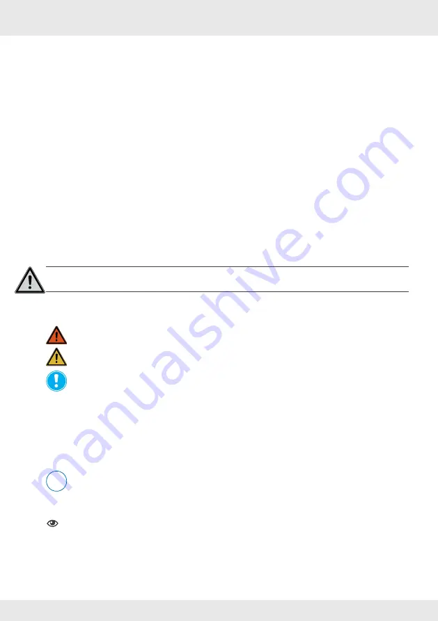
The safety and warning instructions in these operating instructions have a uniform structure and 

are marked with a symbol on the left side of the instruction. A signal word in front of the text also 

indicates the hazard level. If several hazard levels exist, the highest level safety instruction is 

always used.

The safety and warning instructions contain the following information:

SIGNAL WORD

Type and origin of the danger.

 Possible consequences of the danger!

Measures to avoid the danger.

The signal word indicates the severity of the potential danger unless the preventive measures are 

taken:

 WARNING

 means: Possible danger of serious injury or death.

 CAUTION

 means: Direct danger of minor/significant injury.


NOTICE 

means: Direct or possible risk of property damage due to an adverse event.

If you see these signs, ensure you observe the described measures to prevent possible hazards 

and/or damage.

Other symbols used in this documentation

In addition to the safety instructions, the following symbols are used:

 A 

TIP

 symbol indicates practical and useful tips for handling your controller.

► 

Action required:

 This prompts the user to perform a specific action.


Check the results:

 This requires to check the results of the action you have performed.


Action focus:

 To be taken into account in the corresponding step.

1.2  Safety instructions

The operating instructions are part of your MZ-Home controller and must be available at all times 

(see www.inventer.eu/downloads). When handing the system to a third party, the information 

regarding access to the operating instructions must be handed over also.

i

!

Summary of Contents for MZ-Home

Page 1: ...www inventer eu Operating Instructions MZ Home Control device ...

Page 2: ...e no guarantee of compliance can be provided This documentation describes the functionality of the standard scope For reasons of clarity the documentation does not purport to cover all details on all types of the product and cannot cover every conceivable scenario for commissioning operation cleaning and care The illustrations in this document may differ slightly from the design of the product tha...

Page 3: ...ay 19 4 3 settings main menu 20 4 4 Change language 21 4 5 Switching ventilation devices on and off globally 22 4 6 Programming the 7 day timer 23 4 7 Activate deactivate external interface 27 4 8 Define limit value for humidity and temperature sensor 29 4 9 Set interval for filter change 30 4 10 Confirm filter change 31 4 11 Define output levels 32 4 12 Call up operating hours 33 4 13 Making sett...

Page 4: ...of the potential danger unless the preventive measures are taken WARNING means Possible danger of serious injury or death CAUTION means Direct danger of minor significant injury NOTICE means Direct or possible risk of property damage due to an adverse event If you see these signs ensure you observe the described measures to prevent possible hazards and or damage Other symbols used in this document...

Page 5: ...VENTer GmbH in this documentation Changes or modifications to the units are not permitted Your ventilation system is exclusively designed for use in ambient temperatures between 20 and 50 C Proper operation and maintenance are required for trouble free and safe operation of the equipment system These operating instructions are only valid in conjunction with the operating instructions of the corres...

Page 6: ...ed Demand based ventilation via sensor technology CO2 sensor VOC sensor1 NO or Integration of a safety device e g pressure monitor NC with simultaneous operation of the ventilation devices with fireplaces Integration of the MZ Home controller into an existing building management system via an analogue input DC voltage Features Intelligent Clust Air technology for control of up to four different ar...

Page 7: ... ventilation areas zones Each Clust Air module is assigned to a zone and can be controlled separately A Clust Air module enables the control of up to four inVENTer ventilation devices with heat recovery and the connection of another external sensor digital or analogue The Clust Air module contains a humidity and temperature sensor It is installed in separate housing in the room air flow and connec...

Page 8: ... level can be set manually or via a 7 day timer Due to the automatic humidity monitoring the controller also has demand controlled ventilation if the interior humidity values are too high If connected the information transmitted to the corresponding Clust Air module by means of ex ternal sensors e g CO2 sensor is also included in the control of the ventilation devices in a zone Figure 3 MZ Home co...

Page 9: ...ect Continuous ventilation to cool the room on summer nights or to quickly remove stale or humid indoor air 70 s LED LED Drücken Press Premere Appuyer 70 s LED Drücken Press Premere Appuyer i MZ Home controller without connected external interface If no sensor is connected the operating modes heat recovery continuous ventilation and OFF as well as the pause function can be set individually for eac...

Page 10: ...on units on the Clust Air module to continuous ventilation mode Change all ventilation units on the Clust Air module to the originally set operating mode If the predefined limit value can be changed on the corresponding sensor is exceeded the sensor transmits a control signal to the respective Clust Air module The controller then switches all ventilation devices connected to the Clust Air module t...

Page 11: ...ding The responsible chimney sweep and or building planner decides which measures need to be carried out If an external pressure sensor 4 Pa pressure sensor is integrated the air pressure in the interior is continuously monitored As soon as this exceeds the safety relevant limit the sensor transmits this to the controller This then switches all connected ventilation devices off The function remain...

Page 12: ... management unit for each Clust Air module The control voltage should have a resolution of 10 bits Depending on the control voltage the following functions are available Function Control voltage V DC Manual control 0 00 U 0 50 Pause function 1 00 U 1 50 Heat recovery output level 1 2 00 U 2 50 Heat recovery output level 2 3 00 U 3 50 Heat recovery output level 3 4 00 U 4 50 Continuous ventilation ...

Page 13: ...n level 1 All zones 25 Ventilation level 2 All zones 35 Ventilation level 3 All zones 60 Ventilation level _EF All zones 75 Operating mode Heat recovery All zones Limits Humidity All zones 80 7 day timer Zone 1 n All zones OFF Operating mode All weekdays Heat recovery Ventilation level All weekdays 1 Inputs Zone 1 n All zones OFF Filter change Interval 14 weeks Display Screen brightness 99 Interva...

Page 14: ...ht of the bar indicates the output level at which the controller is set at the time in question Display unit The display unit in the upper part of the operating unit is a liquid crystal display with backlighting It consists of four lines of 20 characters each and displays functions and parameters The screen display switches off automatically after 20 seconds without operation Navigation arrows The...

Page 15: ...l panel to select the menu Navigation arrow You reach the manual control Here the 7 day timer settings can be overridden for 1 8 hours When the 7 day timer is deactivated the output level and operating mode are set here Navigation arrow You reach the following main menus Zone display main menu 4 2 Settings main menu 4 3 ff Navigation arrow You switch through the main menus in reverse To return fro...

Page 16: ... z o n e 1 s e t t i n g s 7 d a y t i m e r 4 6 z o n e 4 V E N T t r h L V a c t 2 2 C 4 3 s e t 8 0 z o n e 1 H R t r h L V a c t 2 9 C 3 2 s e t 8 0 o u t p u t z o n e 4 o u t p u t m o d e V E N T i n t e r v a l 0 4 h f i l t e r c h f i l t e r c h i n t e r v a l r e s i d u s e t t i n g s l i m i t s s e t t i n g s f i l t e r c h a n g e s e t t i n g s o u t p u t l e v e l s 4 8 4 9...

Page 17: ...m e r o n 7 d a y t i m e r M o 0 2 0 4 h V E N T L V 7 d a y t i m e r a p p l y d a t a t o e v e r y d a y y e s o k l a n g u a g e e n g l i s h h a n g e h a n g e d 1 4 w e e k s 8 w e e k s o f f i r e p l s w s w N C e v e l s 7 5 e v e l s 2 5 3 5 6 0 l i m i t s z o n e 4 h u m i d i t y 8 0 n e 1 8 0 m e r o f f h o u r s r u n z o n e 1 5 0 h z o n e 2 5 0 h z o n e 3 5 0 h h o u r s ...

Page 18: ...er switches to continuous ventilation mode after the pause Requirements The start screen is displayed Touch the navigation arrow ÖThe output main menu is displayed Select with the navigation arrows to select the zone Use the navigation arrow to select the menu item output ÖThe output level indicator flashes Touch the navigation arrows to set the output level i 4 Operation 4 1 Carry out manual cont...

Page 19: ...s on the control panel to select the menu Navigation arrow You select the ventilation zone for which the parameters are dis played Navigation arrow The settings main menuappears Navigation arrow You return to the start screen z o n e 1 V E N T t r h L V a c t 2 4 C 3 2 s e t 8 0 Selected zone Ventilation level in which the ventila tion devices of the zone are currently running Currently set output...

Page 20: ...uching the navigation arrow to open the menu displayed on the screen Settings can be made Call up the settings main menu language switch off all ventilation units 7 day timer inputs limits filter change output levels hours run display date time information sensor activation Requirements The start screen is displayed Touch the navigation arrow three times Ö The settings main menu is called up s e t...

Page 21: ...ed Touch the navigation arrow ÖThe language submenu is called up Touch the navigation arrow ÖThe marker arrow points to the currently set language Use the navigation arrow to select the desired language e g English Confirm the selection e g English with the navigation arrow ÖThe marker arrow points to the menu item language ÖThe selected language is set Touch the navigation arrow to return to the ...

Page 22: ...urn to the settings menu Ö You have switched on off all ventilation units connected to the control unit at the same time Requirements You are in the settings main menu Touch the navigation arrow until the menu item all fans off is displayed Touch the navigation arrow ÖThe all fans off menu is called up Use navigation arrows to select the desired option Touch the navigation arrow to activate the de...

Page 23: ... Use the navigation arrow to select the zone to be activated e g zone 1 ÖThe marker arrow points to the currently selected zone Touch the navigation arrow ÖThe display of the currently set parameter flashes Selected option On Off Display Confirm option Touch the navigation arrow to activate the 7 day timer Touch the navigation arrow to confirm the selection Ö The 7 day timer submenu in which setti...

Page 24: ...ep 2 Set time interval Step 3 Set ventilation mode Step 4 Set fan speed Step 5 Transfer the data of the set weekday all time intervals for all weekdays in the corre sponding zone Step 1 Select weekday Touch the navigation arrow ÖThe marker arrow is set to the next menu item that can be set Requirements The 7 day timer for the selected zone is active Use the navigation arrow to select the day menu ...

Page 25: ...ion arrow to confirm the selection ÖThe ventilation mode indicator flashes Use the navigation arrow to select the desired ventilation mode Touch the navigation arrow to confirm the selection ÖThe flashing stops Ö You have set the ventilation mode Requirements The 7 day timer for the selected zone is active Use the navigation arrow to select the menu item time Interval Touch the navigation arrow to...

Page 26: ...sible to transfer individual intervals The data transfer only takes place for the current zone Each zone must be programmed separately By touching the navigation arrow you can exit the menu without saving the changes You return to the activated 7 day timer menu and can make further settings on the 7 day timer Touch the navigation arrow repeatedly until a new screen opens Use the navigation arrow t...

Page 27: ... sensor is installed and the input fireplace switch is selected it must also be set whether it is a normally closed contact NC or normally open contact NO Activate interface Touch the navigation arrow ÖThe Inputs submenu is called up Use the navigation arrow to select the zone whose interface is assigned for example zone 2 Touch the navigation arrow until the menu item Inputs is displayed Use the ...

Page 28: ...rface is to be deactivated for example zone 2 Use the navigation arrow to select the off input Ö You have deactivated the interface Requirements You are in the Inputs submenu The external interface is assigned to a pressure sensor Ö You have assigned the function to the switch contact Requirements You are in the settings main menu The external interface is activated Deactivating the interface Opti...

Page 29: ... selection Use the navigation arrow to select the zone whose limit value is to be set ÖThe displayed zone is active Use the navigation arrow to select the menu item humidity ÖThe marker arrow points to the humidity menu item Touch the navigation arrow ÖThe currently set limit value parameter flashes Touch the navigation arrow to decrease increase the limit value ÖThe limit value is changed Confirm...

Page 30: ... Touch the navigation arrow ÖThe filter change submenu is called up Use the navigation arrow to select the menu item interval Touch the navigation arrow to confirm the selection ÖThe interval indicator flashes Touch the navigation arrow to decrease increase the number of weeks between filter changes ÖThe interval indicator is set to the change interval Requirements You are in the settings main men...

Page 31: ...arrow to select the menu item filter changed Touch the navigation arrow to confirm the selection ÖThe residual display is reset to the change interval i Requirements The filter change indicator appears on the start screen Ö You have confirmed the filter change To change the change interval after confirming you can select the interval menu item directly and change the interval Then switch again to ...

Page 32: ...tion arrow ÖThe output level submenu is called up Touch the navigation arrow until the output levels menu item is displayed Touch the navigation arrow to increase decrease the fan speed in 5 steps Touch the navigation arrow to confirm the selection ÖThe flashing stops Ö You have set the output levels for heat recovery and ventilation Use the navigation arrow to select the output level you want to ...

Page 33: ...ing 4 12 Call up operating hours Touch the navigation arrow ÖThe hours run submenu is called up Use the navigation arrow to select the zone whose operating hours you want to view Requirements You are in the output level submenu Requirements You are in the settings main menu Touch the navigation arrow until the menu item hours run is displayed Ö You can view the operating hours of the zone Touch th...

Page 34: ...ness menu item Touch the navigation arrow ÖThe current brightness value flashes Touch the navigation arrow or to increase or decrease the brightness Touch the navigation arrow to confirm the selection Ö The flashing stops Touch the navigation arrow Requirements You are in the settings main menu Setting the brightness of the backlight Ö The display submenu is called up Ö The current display setting...

Page 35: ... navigation arrow ÖThe interval indicator flashes Touch the navigation arrow to shorten lengthen the display duration Touch the navigation arrow to confirm the selection Ö The flashing stops Touch the navigation arrow Adjusting the duration of the backlight Requirements You are in the display submenu Ö You have adjusted the duration of the backlight i Ö The date time submenu is called up Requireme...

Page 36: ...submenu Ö You have set the current date Step 1 Set date Requirements You are in the date time submenu Use the navigation arrows to navigate between the date time and day of the week No value should flash for this purpose Using the navigation arrows you can switch within a line e g day month and year The currently selected value flashes The MZ Home controller interprets the change to another value ...

Page 37: ... ÖYou are back in the date time submenu ÖThe flashing stops Use the navigation arrow to select the menu item time ÖThe marker arrow points to the time menu item Use the navigation arrow to select the day menu item ÖThe marker arrow points to the menu item day Requirements You are in the date time submenu Step 3 Set up day Requirements You are in the date time submenu Ö You have set the current day...

Page 38: ...is displayed Touch the navigation arrow ÖThe standard settings submenu is called up Touch the navigation arrow to reset the MZ Home controller to the factory settings ÖThe MZ Home performs a function test Ö The start screen is then displayed Touch the navigation arrow to exit the factory settings submenu no reset Ö The settings main menu is displayed Requirements You are in the settings main menu ...

Page 39: ...vation menu item is displayed Touch the navigation arrow ÖThe sensor activation submenu is called up Use the navigation arrow to select the zone whose sensor is active On for example zone 2 ÖThe marker arrow points to the zone Touch the navigation arrow to deactivate the sensor Off Touch the navigation arrow to confirm the selection and move to the next zone i Requirements You are in the settings ...

Page 40: ...ructions Cleaning agents NOTICE The MZ Home controller has a scratch sensitive acrylic glass surface and plastic surfaces To prevent damage to the surface do not use sand soda acid or chlorine based cleaning agents A commercially available detergent in warm water can be used for cleaning The following tools may be used for cleaning lint free soft cloth soft brush Cleaning recommendations The tasks...

Page 41: ...n system Component Item number Operating unit MZ Home operating unit white 2006 0103 Clust Air module Clust Air module CAM17 1003 0119 MZ Home control module 3002 0258 Humidity temperature sensor FTS15 MZ 3002 0264 Sensor technology optional CO2 sensor CS1 1004 0145 Switching power supply units Switching power supply unit NT15 MZ for DIN rail installation 3002 0260 ...

Page 42: ...le faulty Briefly disconnect the controller from the power supply no sensor indicator flashes permanently on the start screen No humidity and tempera ture sensor connected to Clust Air module Deactivate the sensor of the affected Clust Air module Faulty measuring results of the humidi ty sensor Insufficient flow through the sensor Check that the ventilation slots and the sensor are facing the same...

Page 43: ...able at www inventer eu guarantee 9 Service Complaints Check the delivery for completeness and transport damage upon receipt using the delivery note Report missing items immediately and at the latest within 14 days to your supplier distributor or factory representative Guarantee and warranty claims In the case of a guarantee or warranty claim contact your local distributor or factory representa ti...

Page 44: ...Item number 5020 0020 Version 1 0 06 2022 Subject to modifications We accept no liability for printing errors inVENTer GmbH Ortsstraße 4a 07751 Löberschütz Germany www inventer eu ...

Reviews: