background image

Ventilation system

inVENTer PAX – Standard set

Installation and operating instructions

Summary of Contents for PAX Standard set

Page 1: ...Ventilation system inVENTer PAX Standard set Installation and operating instructions ...

Page 2: ...his documentation has been checked for compliance with the described hardware and software Nevertheless deviations may still occur therefore no guarantee of compliance can be provided This documentation describes the functionality of the standard scope The documentation does not purport to cover all details on all types of the product and cannot cover every con ceivable scenario for installation a...

Page 3: ...3 inVENTer PAX standard set Installation and operating instructions ...

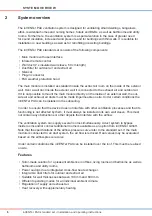
Page 4: ... 4 2 Create wall opening drill holes 18 4 3 Install the mounting plate 19 4 4 Insert the wall ducts 19 4 5 Mount the main module 21 4 6 Connect the main module 24 4 7 Mount the weather protection hood 26 5 Operation 28 5 1 Open grille cover 28 5 2 Operating the ventilation unit via user interface on the main module 28 5 3 Operating the ventilation unit with infrared remote control 31 6 Cleaning an...

Page 5: ... potential hazard unless the preventative measures are taken DANGER indicates Direct danger of serious injury or death WARNING indicates Imminent danger of serious injury or death CAUTION indicates Imminent or possible risk of minor significant injury NOTICE indicates Imminent or possible damage to the property due to an adverse event state Other symbols used in this documentation In addition to t...

Page 6: ...truction project The volume of supply air should match the volume of extract air We recommend an external air supply for inVENTer PAX This may be realised by appropriate overflow measures an air gap of about 10 mm below the door unscrew the hinges by 5 mm use a ventilation grille or similar DANGER When laying the power supply cable observe the requirements of protection class II DANGER Ensure that...

Page 7: ...nst dust until after all construction works are complete Qualified personnel The inVENTer PAX complies with the applicable technical safety requirements and standards for household and similar electrical appliances It may only be installed set up and operated in conjunction with this documentation Installation electrical connection and set up of the equip ment may only be performed by qualified pe...

Page 8: ...aust air ducts must be made impermeable on site Under certain conditions the inVENTer PAX can be installed in the subceiling In order to ensure that the device does not interfere with other ventilation processes and that its functioning is not affected by them it must always be installed in its own wall sleeve This must not contain any obstructions or other objects that interfere with the airflow ...

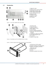
Page 9: ...ht 4 Filter change indicator light 5 User interface grille cover 6 Extract air inlet 7 Exhaust air outlet 8 Outdoor air inlet 9 Front panel 1 Mounting plate 2 Supply air adaptor 3 Main ON OFF switch 4 User interface 5 Lever to release front panel 6 Opening for the extract air filter cartridge 7 Cartridge for extract air dust filter 8 User interface grille cover 9 Front panel 10 Outdoor air dust fi...

Page 10: ...d and the operating mode selected via the remote control or the usert interface directly on the main module Setting and autocalibrating the airflow Figure 4 Airflow on the inVENTer PAX main module The air flow rate can be changed in three operating levels Low airflow 30 m h Moderate airflow 52 m h High airflow 78 m h Balanced control of the air flow rates low moderate high is achieved by autocalibrat...

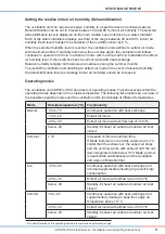
Page 11: ...odes The ventilation unit inVENTer PAX provides four operating modes Functional scope within the operating modes depends on the outside temperature The following list provides an overview of the possible operating modes and the ventilation unit s functionality at different temperatures Mode Outside temperature C Functionality Normal 35 to 15 Continuous operation with heat exchange 15 to 20 Extract...

Page 12: ...erface is located on the main module The user interface is an electronic program ming unit for controlling all the functions of the inVENTer PAX ventilation unit In addition to the functions selectable by remote control it offers the possibility to set the limit value of relative humidity set the filter change interval and autocalibrtes the airflow 2 3 4 5 6 1 1 Fan button for setting the flow rat...

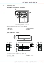
Page 13: ...predetermined minimum distances on both sides of the wall see dimensional drawing 1 Minimum distance to adjacent components on the exterior wall 250 mm from hole center 2 Minimum distance to adjacent components on the interior wall 85 mm from hole center 3 Distance between exhaust air outlet and outdoor air inlet 170 mm 4 Minimum distance between two ventilation units to avoid the mixing of outdoo...

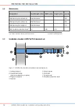
Page 14: ...ning for supply air Wall thickness 110 PAX weather protection hood2 52 398 214 1 incl render insulation masonry and inner structure 2 optional in vertical alignment 3 3 Installation situation inVENTer PAX standard set Figure 7 InVENTer Pax standard set installed horizontal alignment 160 1 7 6 5 4 8 3 2 1 Ceiling interior 2 Suspended ceiling may be realised as an option 3 Plug in Connector 4 Silenc...

Page 15: ...al drawing inVENTer PAX wall openings inVENTer PAX main module Figure 9 Dimensional drawing Main module inVENTer PAX 720 595 85 85 85 Ø100 Ø100 Ø100 85 170 167 191 340 85 1 2 3 1 Supply air outlet 2 Exhaust air outlet 3 Outdoor air inlet 85 4 85 170 Ø160 1 Ø160 2 85 Ø160 1 2 3 Exterior wall outdoor air exhaust air 1 Interior wall 2 Wall opening 3 Drilling template 4 Ceiling ...

Page 16: ...tions for the connection over the roof Observe the following installation condidtions to avoid damages to the product The roof hoods must overtower the local snow depth and be carried out driving rain resistant Insulate the outdoor and exhaust air ducts according to applicable rules of engineering imper meable Thus due to cold outdoor temperature occuring condensate at the outer side of the outdoo...

Page 17: ... upon receipt using the delivery note Report missing items immediately and at the latest within 14 days to your supplier distributor or factory representative Figure 11 inVENTer PAX standard set F R O N T S I D E 1 5 7 2 6 4 3 8 1 Drilling template 2 Silencer 3 Main module with remote control 4 Mounting plate 5 Plug in connector 6 Installation and operating instructions 7 Wall duct 8 Weather prote...

Page 18: ...Milling drill with Ø 160 mm drilling bit Ø 8 mm wall chaser adhesive tape marker pen Requirements The masonry must be dry and in a load bearing condition There must be no load bearing elements at the location of the planned wall openings Secure the drilling template to the ceiling with adhesive tape Mark the position of the mounting plate at the corners of the drilling template red circles Mark th...

Page 19: ...plate is installed 4 4 Insert the wall ducts NOTICE Accumulation of condensate in the wall duct and interruption of the thermal insulation composite system Damage to exterior wall masonry and the building structure Attach the wall ducts with a slope of 1 2 to the exterior wall Replace the wall construction as far as the wall ducts Observe the necessary barrier levels Screw the mounting plate to th...

Page 20: ...nsulating sleeves to a size of the wall thickness X Insert the folded spiral seam ducts into the insulating sleeves Make sure that the folded spiral seam duct is flush with the insulating sleeve on one side 1 2 10 X 10 X Insert the wall ducts into the wall openings from the interior Ensure that the wall ducts are flush with the interior wall Cut off the insulating sleeves flus with the exterior wa...

Page 21: ...for screws ecrew driver sealing tape adhesive tape permanently elastic sealing compound 200 mm long bit PH2 Requirements The wall duct is mounted The mounting plate is installed Lay the power cable 230 V AC to the mounting plate for the main module NOTICE No sealing tape Reduction in airflow Fit sealing tape to the casing on the outdoor air exhaust air adaptor side Attach the sealing tape cicumfer...

Page 22: ...rrow on the casing sideways 2 Ö Ö The front panel is released 1 2 2 Unclip the front panel from the roller catches on both sides Pull up and remove the front panel Remove the screws from the terminal box cover Detach the terminal box cover Turn the main module on its side 1 Leed the power cable through the main mod ule to the terminal box on the main module s opposite side 2 3 Ensure that the powe...

Page 23: ...or condensate penetration into insulating sleeves Fix the folded spiral seam ducts by applying counter pressure from the outside Ö Ö The main module is installed Lay the power cable inside one of the cable conduits Affix the power cable inside the selected cable conduit with adhesive tape Seal the cable entry red arrow with perma nently elastic sealing compound Press the main module against the mo...

Page 24: ... OFF switch forms part of the hard wiring in the unit in accordance with the applicable regulations We recommend installing a separate power circuit with circuit breaker for the ventilation unit Figure 12 Electrical connection of the inVENTer PAX main module The inVENTer PAX is connected directly to the 230 V AC mains Electrical connection takes place inside the mian module s terminal box Requirem...

Page 25: ...module with 2 screws Snap the front panel into place in the roller catches red marking on both sides of the casing Slide the lever red arrow on the casing sideways 1 Ö Ö The front panel is locked Fold the grille cover upwards until it snaps in 2 2 1 1 Ö Ö The main module is connected Press the main ON OFF switch into position I Ö Ö The ventilation unit is switched on ...

Page 26: ... the plaster surface around the weather protection hood before installing Consult your planner Spirit level marker pen drilling machine with drilling bit Ø 8 mm screw driver rawl plugs wall plugs for insulation when exterior wall is insulated permanently elastic outdoor sealing compound Requirements The exterior wall is finished and even The wall duct is inserted and shortened NOTICE Drip rails on...

Page 27: ...op Ö Ö The Pax weather protection hood is mounted On the base plate s exterior wall side attach the 9 mm sealing tape circumferentially on the outer edge flush with the openings for the wall duct Ensure that thesealing tape does not protrude the openings Screw the base plate to the exterior wall with four screws Hook the cover from the underneath into the upper drip rail s slots red arrows Fold th...

Page 28: ...interface on the main module 1 Starting Setting standby the ventilation unit Page 28 2 Setting the operating mode Page 29 3 Setting the flow rate Page 29 4 Autocalibrating the airflow Page 29 5 Setting the dehumidification Page 30 6 Setting to default Page 30 Starting Setting standby the ventilation unit Requirements The ventilation unit is in standby started The grille cover is unclipped see sect...

Page 29: ...e airflow is not adapted After changes installation carry out an autocalibration to adjust the ventilation systems to the changed parameters Requirements The ventilation unit is switched on All doors and windows are closed The grille cover is unclipped see section 5 1 Press the button repeatedly until the indicator light of the desired operating mode is lit Press the button repeatedly until the in...

Page 30: ... ventilation unit is switched on The grille cover is unclipped see section 5 1 Setting to default The settings for airflow rates and air dampers can be restored to factory default Requirements The ventilation unit is in standby The grille cover is unclipped see section 5 1 Ö Ö Factory defaults have been restored Press the button repeatedly Ö Ö Dehumidification indicator light illuminates on user int...

Page 31: ...Ö The ventilation unit is started in standby Setting the operating mode Requirements The ventilation unit is switched on Ö Ö The operating mode is set Setting the flow rate Requirements The ventilation unit is switched on Ö Ö The flow rate is set Press the button Ö Ö The ventilation unit is started Press the button once again Ö Ö The ventilation unit is in standby Press the button with the symbol ...

Page 32: ...ents NOTICE The surface of the ventilation unit is heat sensitive and susceptible to scratching Damage to the surface Do not use sand soda acid or chlorine based cleaning agents The water temperature for cleaning must be below 60 C A commercially available detergent in warm water can be used for cleaning the front panel and the casing The following tools may be used for cleaning lint free soft clo...

Page 33: ...cover down 1 Slide the lever red arrow on the casing side ways 2 Ö Ö The front panel is released 1 2 2 Unclip the front panel from the roller catches on both sides Pull down and remove the front panel Switching on Press the main ON OFF switch into position I Ö Ö The ventilation unit is switched on via the main ON OFF switch Or Switching off Press the main ON OFF switch into position 0 Ö Ö The vent...

Page 34: ...nge interval may only be set via the main module s user interface Setting by remote control is not possible Requirements The ventilation unit is switched on The grille cover is unclipped see section 5 1 Slide the lever red arrow on the casing sideways 1 Ö Ö The front panel is locked Fold the grille cover upwards until it snaps in 2 2 1 1 Ö Ö The ventilation unit is switched on off via the main ON ...

Page 35: ... Filter change LED Operating mode LED 90 180 270 365 Ö Ö The filter change interval is set Press the button repeatedly until you reach the required time interval Ö Ö The buzzer sounds for each selected time interval Ö Ö The currently selected time interval is indicated by the flashing airflow filter and mode LEDs see table below 365 270 180 90 Press the buttons and simultaneously for 3 seconds ...

Page 36: ...ation unit is switched off via the main ON OFF switch see section 6 1 Unclip locking bracket to the side Press together the tabs red arrows on the outdoor air filter cartridge Ö Ö The outdoor air filter cartridge unclips Pull down the outdoor air filter cartridge 1 Remove the filter cartridge s cover Replace the ourtdoor air filter Insert the cover into the filter cartridge 1 2 Clean the opening for...

Page 37: ...taminated filter Insert the new filter into the cover for the filter cartridge Insert the extract air filter cover into the main module 2 2 1 Snap the front panel into place in the roller catches red marking on both sides of the casing Slide the lever red arrow on the casing sideways 1 Ö Ö The front panel is locked Fold the grille cover upwards until it snaps in 2 Ö Ö You have replaced the filters ...

Page 38: ...tandard sound level differential dB supply air area 77 Output level Low Moderate High only ex haust air Airflow free blowing m h 30 52 78 90 Noise emissien rated dB A 19 22 29 35 Power consumption W 3 5 8 0 18 0 25 0 Max Power consumption with heating W 375 375 375 Heat recovery η w 0 8 0 78 0 75 Leakage loss 5 Energy efficiency class A Wall thickness with render mm 100 600 Wall opening mm 2 x Ø 1...

Page 39: ...in mm 398 x 214 x 52 Weight g 1210 Colour White RAL9016 Grey RAL9006 Nord RAL7011 1 On request the PAX weather protection hood is available in vertical alignment and or custom colour Airflow curve inVENTer PAX Figure 13 Airflow pressure curve inVENTer PAX free blowing 10 20 30 40 50 60 70 80 90 0 100 50 150 250 200 Druckdifferenz Pa 1 2 3 Luftvolumenstrom m h 1 Fan level 1 2 Fan level 2 3 Fan leve...

Page 40: ...e RAL9016 1508 3001 Weather protection hood PAX h grey RAL9006 1508 3002 Weather protection hood PAX h Nord RAL7011 1508 0079 1 On request the PAX weather protection hood is available in vertical alignment and or custom colour 9 Accessories Component Order number Folded spiral seam duct DN100x995 1506 3002 Disc valve supply air DN100 steel white 3006 3001 Silencer DN100 telescopic 380 500 3008 300...

Page 41: ...circuit breaker Orange Mainte nance indicator light flashing End of maintenance interval has been reached Replace dust filters Press filter change button Low airflow Filters contaminated or defective Replace dust filters Decrease the filter change interval Disposal Dispose of the product in compliance with the applicable national regulations The products described in these installation and operating ...

Page 42: ...rranty is available at www inventer eu guarantee 12 Service Claims Check the delivery for completeness and transport damage upon receipt using the delivery note Report missing items immediately and at the latest within 14 days to your supplier distributor or factory representative Warranty and guarantee claims In the case of a warranty or guarantee claim contact your local distributor or factory r...

Page 43: ...ÜTZ TELEPHONE 49 0 36427 211 0 FAX 49 0 36427 211 113 EMAIL INFO INVENTER DE HOMEPAGE WWW INVENTER EU CEO ANNETT WETTIG VAT ID NUMBER DE 815494982 JENA DISTRICT COURT HRB 510380 PICTURE CREDITS ALL RIGHTS RESERVED INVENTER GMBH 2016 17 SUBJECT TO MODIFICATIONS ALL INFORMATION IS SUPPLIED WITHOUT GUARANTEE NO LIABILITY IS ACCEPTED FOR PRINTING ERRORS Company details ...

Page 44: ... Ortsstraße 4a D 07751 Löberschütz Telephone 49 0 36427 211 0 Fax 49 0 36427 211 113 Email info inventer de www inventer eu Version dated 08 2017 Subject to modifications Order number 5015 0005 inVENTer GmbH 2016 17 ...

Reviews: