24
ASSEMBLY AND INSTALLATION
inVENTer PAX standard set
•
Installation and operating instructions
4.6
Connect the main module
DANGER
Exposed electrical components.
Electric shock and injury due to live components (230 V, 50 Hz)!
► Before working on electrical installations, disconnect affected equipment from the power supply.
►
Do not lay or connect live cables.
► Installation and electrical connection must only be performed by qualified and trained personnel.
TIP:
The ventilation unit is equipped with an internal ON/OFF switch (circuit breaker), which
disconnects all poles of the unit from the power supply in accordance with overvoltage
category III. The ON/OFF switch forms part of the hard wiring in the unit in accordance with the
applicable regulations. We recommend installing a separate power circuit with circuit breaker for
the ventilation unit.
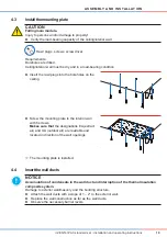
Figure 12: Electrical connection of the inVENTer PAX main module.
The inVENTer PAX is connected directly to the 230 V AC mains. Electrical connection takes
place inside the mian module’s terminal box.
Requirements:
The main module is installed. The power supply is disconnected.
Power cable
Lustre terminal
Terminal
Colour Terminal
Phase
brown
L
Neutral conductor blue
N
►
Cut the power cable to size (Dismantling: 7 mm).
►
Connect the power cable, 230 V AC, to the lustre
terminal inside the terminal box.
N
L
4
1
2
3
1 Stain relief
2 Lustre terminal
3 Main ON/OFF switch
4 Power cable, 2-pole
►
Secure the power cable with the cable stain
relief (red arrow) to the casing.


