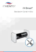
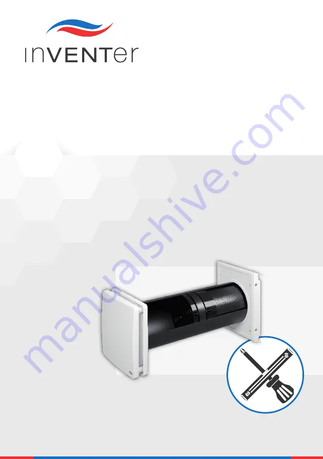
background image

iV-Smart

+

Standard • Corner •

 Ohio

Summary of Contents for sMove

Page 1: ...iV Smart Standard Corner Ohio ...

Page 2: ... etc The content of this documentation has been checked for compliance with the described hardware and software Nevertheless deviations may still occur there fore no guarantee of compliance can be provided This documentation describes the functionality of the standard scope The documentation does not purport to cover all details on all types of the product and cannot cover every conceivable scenar...

Page 3: ...or energy related products 14 4 Preparing for installation Installation position 15 5 iV Smart ventilation unit 16 5 1 Construction 16 5 2 Dimensions 17 5 3 Assembly and installation 20 6 iV Smart Corner ventilation unit 28 6 1 Construction 28 6 2 Dimensions 29 6 3 Assembly and installation 33 7 iV Smart Ohio ventilation unit 41 7 1 Construction 41 7 2 Dimensions 42 7 3 Assembly and installation 4...

Page 4: ...potential hazard unless the preventative measures are taken WARNING indicates Imminent danger of serious injury or death CAUTION indicates Imminent or possible risk of minor significant injury CAUTION indicates Imminent or possible risk of minor significant injury due to electricity Before carrying out any work on steps stressed with this symbol disconnect the power supply NOTICE indicates Imminen...

Page 5: ...lation CAUTION Installation of the system may only be performed by qualified personnel Before starting work you should have a ventilation concept from which the number of ventilation units their position the ventilation principle cross ventilation individual room ventilation extraction and the relevant controllers can be determined The exact positioning of the units and controllers must be determi...

Page 6: ...tact with sharp or pointed objects e g rings Wiring Electrical connection of the fan CAUTION Electrical connection of the system may only be performed by qualified personnel NOTICE Your ventilation unit operates with a safety extra low voltage SELV and an operating voltage of 6 16 V DC The ventilation unit must therefore not be connected directly to the 230 V mains but must always be connected via...

Page 7: ... meaning of the safety notices in this documen tation are persons who are authorised to install put it into operation and identify equipment systems and circuits in accordance with established safety procedures Conformity The ventilation unit complies with the applicable technical safety requirements and standards for household and similar electrical appliances They are conform to the following Eu...

Page 8: ...em controllers1 sMove s4 sMove s8 MZ Home Components Inner cover inkl dust filter of class G4 Thermal accumulator insert thermal accumulator and inVENTron Wall sleeve Exterior closure Pollen micro and activated carbon filter options available Sound and wind protection options available as accessory Models Standard version iV Smart ventilation units with driving rain proof Nova or Smart weather pro...

Page 9: ... S3 according to EN 13141 8 max 30 air flow deviation at 20 Pa In order to ensure the full functioning of the ventilation system throughout the entire year an additional flexible temperature sensor is integrated into the Xenion reversible fan This measures the temperature of the air flow If the temperature falls below 5 C the reversible fan is automatically switched to extract air mode for 4 cycle...

Page 10: ...is an electronic control unit for controlling up to 16 iV Smart ventilation units It is characterised by Clust Air technology multizone control simple installation touch based operation and its versatility The MZ Home controller consists of a control unit and at least one optional up to four Clust Air module s Each Clust Air module can control up to four iV Smart ventilation units in different zon...

Page 11: ...d sound level differential dB Standard 38 49 Corner 39 47 Ohio 34 Heat recovery η w 0 87 Output voltage V DC 6 16 Power consumption W 1 3 Flow based electrical fan capacity W m h 0 15 Protection class EN 61140 III Type of protection EN 60529 IP20 Filter class standard filter EN 779 2012 G4 Air flow sensitivity at 20 Pa EN 13141 8 S3 Frost protection Automatically due to push pull operation up to 2...

Page 12: ...overy ƞt 87 h Maximum flow rate supply air m h 58 i Electric power input W 6 j Sound power level Lwa dB A 44 k Reference flow rate m h 42 l Reference pressure difference Pa 0 m Specific power input SPI W m h 0 15 n Control factor 0 65 o Internal external leakage rate n a p Mixing rate n a q Position of visual filter warning Controller r Regulated supply and exhaust grilles in the facade one direct...

Page 13: ...ve e Thermal efficiency of heat recovery ƞt 87 h Maximum flow rate supply air m h 58 i Electric power input W 6 j Sound power level Lwa dB A 44 k Reference flow rate m h 42 l Reference pressure difference Pa 0 m Specific power input SPI W m h 0 15 n Control factor 1 o Internal external leakage rate n a p Mixing rate n a q Position of visual filter warning Controller r Regulated supply and exhaust ...

Page 14: ...er iV Smart Ohio iV Smart Top iV Smart Sylt Local demand control Manual control MZ Home sMove w sensors sMove with sensors A A 3 3 Label according to EC Directive for energy related products regulation 1254 2014 Germany On the energy label you can find the following information from the product fiche Energy efficiency class Specific energy consumption class Sound power level Lwa Maximum air flow s...

Page 15: ...reas in which direct contact with water spray is possible Observe the following minimum distances for the unit s wall opening 1 between two ventilation units in push pull operation pair in the same room to avoid the mixing of outdoor air and exhaust air 2 to adjacent components on the exterior wall observe insulation shutters Nova protective hood 450 mm from hole center center axis circumferential...

Page 16: ...ve hood base plate 4 Fastening screws for cover 4 x 5 Smart protective hood cover 6 Sealing tape 7 Wall sleeve R D160 8 Recess for fan BUS interior wall side Thermal accumulator insert thermal accumulator and inVENTron 9 Thermal accumulator with insulation 10 Thermal accumulator handle 11 Standard guiding vane broad 12 Xenion reversible fan 13 Slim guiding vane 14 Guiding vane knob 15 BUS plug con...

Page 17: ...23 88 279 313 Flair inner cover V 233x233 612 233 233 1 incl render insulation masonry and inner structure 2 opened Sectional drawing Figure 2 Sectional drawing iV Smart side view 233 61 Ø 160 43 285 10 260 270 1 2 150 1 Inner cover base plate 2 Inner cover panel 3 Wall sleeve R D160 4 Exterior closure Weather protection hood 5 Joint tape 6 Thermal accumulator 7 Standard guiding vane broad 8 Xenio...

Page 18: ...d base plate Figure 4 Dimensioned drawing of Smart protective hood A A 279 A A 23 88 313 21 252 221 148 7 4 x Ø4 8 Ø168 1 Protective hood base plate 2 Exterior wall attachment with Ø 8 mm min 50 mm deep 4 x 3 Protective hood cover 4 Protective grid 5 Drip rail 44 222 56 285 4 x Ø5 180 90 180 1 Protective hood base plate 2 Exterior wall attachment with Ø 8 mm min 50 mm deep 4 x 3 Upper drip rail 4 ...

Page 19: ...148 165 250 180 2 1 3 4 5 6 250 1 250 1 2 450 2 With Smart protective hood With Nova protective hood 1 Wall opening New building Simplex as an option 2 Wall opening Existing buildings 3 Position of protective hood contour 4 Window reveal 5 Door window frame 6 Bottom edge of reveal 3 Inner cover Figure 6 Dimensioned drawing of Flair inner cover V 233x233 1 Inner cover panel 2 Sound insulation optio...

Page 20: ...entilation system Installation instructions 5 3 Assembly and installation Additional required tools and materials 3 x 0 75 mm Cable braided flex 3 x 0 75 mm Wire ferrules with collar Interior wall Exterior wall Ø 6 mm Ø 8 mm Ø 180 mm 0 75 mm ...

Page 21: ...the wall opening Checking the scope of supply 4x 4x 4x 4x M in X ø 180 45 CAM17 MZ Home sMove 3 x 0 75 mm 6 16 V DC 230 V AC 1 2 1 2 3 4 Item no 1506 0068 1506 0069 Item no 1505 0036 1505 0037 Item no 1508 0080 1508 0081 1508 0082 Item no 1508 0062 1508 0063 1508 0069 Item no 1507 0017 X 22 ...

Page 22: ... SMART VENTILATION UNIT iV Smart ventilation system Installation instructions Install the wall sleeve Item no 1506 0068 1506 0069 1 2 1 2 24 h 1 2 5 6 7 8 3 4 X 10 mm 2 X 10 D A B C X 10 D A B C 1 X A B C D ...

Page 23: ...T VENTILATION UNIT iV Smart ventilation system Installation instructions Mount the weather protection hood A Smart protective hood Item no 1508 0062 1508 0063 1508 0069 ø 8 mm 50 mm 5 mm 2 4 x 1 2 4 5 6 7 8 3 4 x ...

Page 24: ...24 IV SMART VENTILATION UNIT iV Smart ventilation system Installation instructions ø 8 mm 50 mm B Nova protective hood Item no 1508 0080 1508 0081 1508 0082 1 2 3 4 5 6 7 8 4 x ...

Page 25: ...ystem Installation instructions Insert thermal accumulator insert and connect the reversible fan A Insert thermal accumulator and inVENTron Item no 1507 0017 Slim Standard X 2 0 0 mm IV III V 3 x 0 75 mm 6 16 V DC 230 V AC X 22 1 2 3 4 6 7 5 8 3 x 0 75 ...

Page 26: ...t ventilation system Installation instructions B Connect the fan BUS to the reversible fan Starting Direction CCW Supply Air SUP Starting Direction CW Extract Air ETA Unit 1 Unit 2 IV V III V IV CW CCW IV V III CW CCW SUP ETA CHECK CCW CW ...

Page 27: ...27 IV SMART VENTILATION UNIT iV Smart ventilation system Installation instructions Attach Flair inner cover Item no 1505 0036 1505 0037 ø 6 mm 40 mm 4 x CLICK 1 2 3 4 5 6 A CLICK B 7 ...

Page 28: ...ner flat duct 9 Opening for wall sleeve 10 Sealing tape 11 Neopor insert Thermal accumulator insert thermal accumulator and inVENTron 12 Wall sleeve R D160 13 Recess for fan BUS interior wall side Flair inner cover 14 Thermal accumulator with insulation 15 Thermal accumulator handle 16 Standard guiding vane broad 17 Xenion reversible fan 18 Slim guiding vane 19 Guiding vane knob Exterior closure R...

Page 29: ...asonry and inner structure 250 Thickness Insulation 120 Wall opening for wall sleeve Wall thick ness1 180 Wall sleeve R D160x495 745 495 745 160 Corner flat duct 90x220x400 D160 400 95 224 Corner flat duct 90x220x500 D160 500 95 224 Reveal grille V 90x220 10 104 281 5 Flair inner cover V 233x233 612 233 233 1 incl render insulation masonry and inner structure 2 opened ...

Page 30: ... mm is max 285 mm 3 Use flat duct Corner 500 if y z is at least 365 mm is max 385 mm 1 Reveal grille 2 Flat duct sliding sleeve 3 Corner flat duct2 3 4 Wall bracket 2x 5 Joint tape 6 Sealing tape 7 Thermal accumulator 8 inVENTron Xenion reversible fan embedded in guiding vanes 9 Wall sleeve 10 Inner cover base plate 11 Inner cover panel A Plaster B Masonry C Window frame D Window casement E Render...

Page 31: ... 2502 110 110 Ø180 2 5 3 155 1 3502 110 110 1 1 Ø180 2 3 4 5 4 Inner cover Figure 10 Dimensioned drawing of Flair inner cover V 233x233 1 Inner cover panel 2 Sound insulation optional 3 Holding plate IC V 233x233 4 Inner cover base plate 5 Spacer 4 x 6 Interior wall attachment with Ø 6 mm min 40 mm deep 4 x 1 Wall opening New building Simplex as an option 2 Corner flat duct contour 3 Bottom edge o...

Page 32: ...eal grille 10 104 281 5 1 28 1 231 2 2 4 5 3 2 x Ø5 1 Upper drip rail 2 Louvres 3 Bottom drip rail 4 Through hole 2 x 5 Condensate drip Figure 12 Dimensioned drawing of Corner flat duct 90x220x400 500 D160 1 Fastening element 2 x 2 Opening for wall sleeve 3 Sound insulation 4 Neopor insert 5 Spacer 2 x 120 Ø 162 400 500 55 95 224 239 1 2 4 3 5 ...

Page 33: ...t ventilation system Installation instructions 6 3 Assembly and installation Additional required tools and materials 3 x 0 75 mm Interior wall Exterior wall Ø 6 mm Ø 8 mm Ø 180 mm Cable braided flex 3 x 0 75 mm Wire ferrules with collar 0 75 mm ...

Page 34: ...y Create the wall opening and lay the fan BUS cable controller ventilation unit 4x 4x 2x 4x 4x Item no 1506 0068 1506 0069 Item no 1505 0036 1505 0037 Item no 1506 0066 1506 0067 Item no 1508 0018 1508 0030 1508 0065 Item no 1507 0017 M in X 45 CAM17 MZ Home sMove 3 x 0 75 mm 6 16 V DC 230 V AC 2 3 4 ø 180 1 2 1 X 35 ...

Page 35: ...SMART CORNER VENTILATION UNIT iV Smart ventilation system Installation instructions Install the wall sleeve Item no 1506 0068 1506 0069 1 2 1 2 24 h 1 2 5 6 7 8 3 4 X 30 mm 2 X 30 D A B C X 30 D A B C 1 X A B ...

Page 36: ...R VENTILATION UNIT iV Smart ventilation system Installation instructions Mount the Corner flat duct Item no 1506 0066 1506 0067 L y z 120 1 2 1 2 ø 8 mm 40 mm L y z 120 1 2 1 2 1 2 3 4 5 6 7 y 250 120 5 15 z 35 30 Ø 120 ...

Page 37: ...37 IV SMART CORNER VENTILATION UNIT iV Smart ventilation system Installation instructions 8 10 mm 5 mm Mount the reveal grille Item no 1508 0030 1508 0065 4 x 9 10 1 2 3 4 A B ...

Page 38: ...on system Installation instructions Insert thermal accumulator insert and connect the reversible fan A Insert thermal accumulator and inVENTron Item no 1507 0017 X 2 0 0 mm IV III V 3 x 0 75 mm 6 16 V DC 230 V AC X 35 1 2 3 4 6 7 5 8 Slim Standard 3 x 0 75 ...

Page 39: ...mart ventilation system Installation instructions B Connect the fan BUS to the reversible fan Starting Direction CCW Supply Air SUP Starting Direction CW Extract Air ETA Unit 1 Unit 2 V III V IV CW CCW IV V III CW CW CCW SUP ETA CHECK CCW CW ...

Page 40: ...40 IV SMART CORNER VENTILATION UNIT iV Smart ventilation system Installation instructions Attach Flair inner cover Item no 1505 0036 1505 0037 ø 6 mm 40 mm 4 x CLICK 1 2 3 4 5 6 A CLICK B 7 ...

Page 41: ...eopor insert 7 Attachment points exterior wall 4 x 8 Opening for wall sleeve 9 Wall sleeve R D160 10 Recess for fan BUS interior wall side Thermal accumulator insert thermal accumulator and inVENTron Flair inner cover 11 Thermal accumulator with insulation 12 Thermal accumulator handle 13 Standard guiding vane broad 14 Xenion reversible fan 15 Slim guiding vane 16 Guiding vane knob 17 BUS plug con...

Page 42: ...ve hood 110 230 247 Flair inner cover V 233x233 612 233 233 1 incl render insulation masonry and inner structure 2 opened Sectional drawing Figure 14 Sectional drawing iV Smart Ohio ventilation unit plan view A Render B Masonry C Plaster 1 Inner cover base plate 2 Inner cover panel 3 Wall sleeve 4 inVENTron Xenion reversible fan embedded in guiding vanes 5 Thermal accumulator 6 Metal sleeve 7 Prot...

Page 43: ...interior wall 2 Observe insulation shutters on exterior wall 1 Wall opening New buildings Simplex as an option 2 Wall opening Existing buildings 3 Position of protective hood contour 4 Window reveal 5 Door window frame 6 Bottom edge of reveal2 Ø180 250 180 5 3 6 4 123 124 2 1 250 1 1 Inner cover panel 2 Sound insulation optional 3 Holding plate IC V 233x233 4 Inner cover base plate 5 Spacer 4 x 6 ...

Page 44: ...gure 17 Dimensioned drawing of Ohio protective hood 247 230 110 4 4 5 6 7 6 5 163 210 227 245 6 105 100 106 114 M4x0 7 4x Ø6 1 2 3 1 Attachment points for protective grille 2 Neopor insert 3 Attachment points exterior wall 4 x 4 Metal sleeve 5 Protective grille 6 Louvres 7 Fastening screws for protective grille 4 x ...

Page 45: ...art ventilation system Installation instructions 7 3 Assembly and installation Additional required tools and materials 3 x 0 75 mm Interior wall Exterior wall Cable braided flex 3 x 0 75 mm Wire ferrules with collar 0 75 mm 6 mm 8 mm 180 mm ...

Page 46: ... instructions Checking the scope of supply 4x 4x 4x 4x 4x Item no 1506 0068 1506 0069 Item no 1505 0036 1505 0037 Item no 1508 0072 Item no 1508 0019 Item no 1507 0017 Create the wall opening M in X 45 CAM17 MZ Home sMove 3 x 0 75 mm 6 16 V DC 230 V AC 2 3 4 ø 180 1 2 1 X 47 ...

Page 47: ...SMART OHIO VENTILATION UNIT iV Smart ventilation system Installation instructions Install the wall sleeve Item no 1506 0068 1506 0069 1 2 1 2 1 2 24 h 5 6 7 8 3 4 X 100 mm 2 X 100 D A B X 100 D A B 1 X A B D ...

Page 48: ...180 Mount the Ohio protective hood Item no 1508 0072 50 mm ø 8 mm 10 mm 10 mm 180 1 2 3 4 5 6 7 8 48 IV SMART OHIO VENTILATION UNIT iV Smart ventilation system Installation instructions ...

Page 49: ...4 x 10 9 11 49 IV SMART OHIO VENTILATION UNIT iV Smart ventilation system Installation instructions ...

Page 50: ...n system Installation instructions Slim Standard Insert thermal accumulator insert and connect the reversible fan A Insert thermal accumulator and inVENTron Item no 1507 0017 X 2 0 0 mm IV III V 3 x 0 75 mm 6 16 V DC 230 V AC X 47 1 2 3 4 6 7 5 8 3 x 0 75 ...

Page 51: ...art ventilation system Installation instructions B Connect the fan BUS to the reversible fan Starting Direction CCW Supply Air SUP Starting Direction CW Extract Air ETA Unit 1 Unit 2 V III V IV CW CCW IV V III CW CW CCW SUP ETA CHECK CCW CW ...

Page 52: ...52 IV SMART OHIO VENTILATION UNIT iV Smart ventilation system Installation instructions Attach Flair inner cover Item no 1505 0036 1505 0037 ø 6 mm 40 mm 4 x CLICK 1 2 3 4 5 6 A CLICK B 7 ...

Page 53: ... requirements during periods of heavy pollution Replace filter if heavily soiled Fans are not operating in paired mode Connect the first fan in extract air mode and the second fan in supply air mode Fan speed is too low Increase the output level Thermal accumulator is soiled Clean the thermal accumulator Noises Foreign body in the fan Remove foreign body from the fan Clean the ventilation unit Fan...

Page 54: ...tainless steel ASA Scrap metal collection Recyclable material collection Smart protective hood Powder coated stainless steel Scrap metal collection Ohio protective hood Powder coated stainless steel Neopor Anodised aluminium Scrap metal collection Recyclable material collection Flat duct PP Recyclable material collection Reveal grille Powder coated stainless steel Scrap metal collection Reversible...

Page 55: ...cts in no way the applicable law Further information about the warranty is available at www inventer eu warranty 10 Service Claims Check the delivery for completeness and transport damage upon receipt using the delivery note Report missing items immediately and at the latest within 14 days to your supplier distributor or factory representative Warranty and guarantee claims In the case of a warrant...

Page 56: ...inal Signification Colour Terminal Colour III GND White V GND Brown CW Blue IV Operating voltage Green IV Operating voltage Green Red V GND Brown III GND White CCW Black Starting direction of reversible fan IV V III III V IV CW CCW CW CCW Starting direction Extract air The locking screws of the green BUS terminal s plug and socket are pointing to the same direction Starting direction Supply air Th...

Page 57: ... Smart ventilation system Installation instructions 12 Appendix 2 Wiring protocol Ventila tion unit Floor Area room and position Ventilation zone CAM Starting direction Supply Extract 1 2 3 4 5 6 7 8 9 10 11 12 13 14 15 16 17 18 19 20 ...

Page 58: ...NT REVERSIBLE FAN iV Smart ventilation system Installation instructions Ventila tion unit Floor Area room and position Ventilation zone CAM Starting direction Supply Extract 21 22 23 24 25 26 27 28 29 30 31 32 33 34 35 36 37 38 39 40 ...

Page 59: ...ELEPHONE 49 0 36427 211 0 FAX 49 0 36427 211 113 EMAIL INFO INVENTER DE HOMEPAGE WWW INVENTER EU CEO ANNETT WETTIG VAT ID NUMBER DE 815494982 JENA DISTRICT COURT HRB 510380 PICTURE CREDITS INVENTER GMBH 2014 18 ALL RIGHTS RESERVED INVENTER GMBH 1999 2018 SUBJECT TO MODIFICATIONS ALL INFORMATION IS SUPPLIED WITHOUT GUARANTEE NO LIABILITY IS ACCEPTED FOR PRINTING ERRORS Company details ...

Page 60: ...www inventer eu Version dated 05 2018 5005 0002 inVENTer GmbH 1999 2018 inVENTer GmbH Ortsstraße 4a D 07751 Löberschütz 49 0 36427 211 0 49 0 36427 211 113 info inventer de ...

Reviews: