background image

5

Kleine Zange

Pliers

Verwenden Sie 2 x C/LR14-Batterie (nicht inkl.)

Use 2 x C/LR14 batteries (not included)

Bauteile sorgsam behandeln, damit sie nicht verloren gehen.

Handle the components with care to prevent them from getting lost.

Maßband oder Zollstock

Tape measure or folding ruler

Werkzeuge für den Aufbau:

Tools for installation:
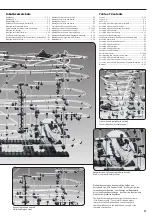
Bauteileübersicht

Parts list

[B1]

[B4]

[S2] 391mm

[S3] 300mm

[S4] 200mm

[S5] 159mm

[S6] 65mm

[C3]

[S1] 600mm

[S1] Achse 600mm

[S1] Shaft 600mm

[S2] Achse 391mm

[S2] Shaft 391mm

[S3] Achse 300mm

[S3] Shaft 300mm

[S4] Achse 200mm

[S4] Shaft 200mm

[S5] Achse 159mm

[S5] Shaft 159mm

[S6] Achse 65mm

[S6] Shaft 65mm

[C3] Abstandshalter

[C3] Spacer

9 x

147+ x

2 x

10 x

11 x

2 x

2 x

12 x

15 x

38 x

9 x

4 x

2 x

3 x

108+ x

168+ x

265+ x

375+ x

300+ x

8 x

20 x

7 x

19 x

8 x

1 x

[A1]

[A2]

[A3]

[A4]

[A5]

[A6]

[A1] Arm

[A1] Arm

[A2] Armhalter A

[A2] Arm holder A

[A3] Aufsteckhülse

[A3] Arm tube

[A4] Armhalter B

[A4] Arm holder B

[A5] Arretierung

[A5] Arm wrench

[A6] Schienenhalterung

[A6] Rail stand

[G1]

[B2]

[Ex2]

[C4]

[Ex5]

[Ex6]

[B3]

[E4]

[G2]

[R2]

[R1] 68.000mm

[E1]

[E2]

[E3]

[Ex1]

[P1]

[G1] Antrieb

[G1] Gear Box

[E1] Aufzugspirale

[E1] Elevator helix

[E2] Aufzugring

[E2] Elevator ring

[E3] Aufzugdeckel

[E3] Elevator cover

[P1] Abzweigung

[P1] Junction

[Ex1] Wippe 

[Ex1] Seesaw

[B2] 

Halter für Bodenplatte (groß)

[B2] Base holder (big)

[B3] 

Halter für Bodenplatte (klein)

[B3] Base holder (small)

[E4] Halter für Aufzug

[E4] Elevator stand

[R1] Schiene (68.000mm)

[R1] Rail (68,000mm)

[G2] Halter für Antrieb

[G2] Gearbox socket

[R2] Schienenverbinder

[R2] Rail joining

Stahlkugeln

Steel balls

[Ex7]

[Ex2] Pendel


[Ex2] Pendulum

[C4] Achsenkappe


[C4] Shaft cap

[Ex5] Kugelfänger


[Ex5] Ball catcher

[Ex6] Gegengewicht


[Ex6] Counterweight

[Ex7] Pendelaufnahme für Stahlkugeln


[Ex7] Pendulum tray for steel balls

[B1] Bodenplatte

[B1] Base plate

[B4] Doppelte Bodenplatte

[B4] Double base plate

Bauteileübersicht - 

Parts List 

13 x

2 x

1 x

1 x

1 x

1 x

1 x

13 x

Summary of Contents for Level 9

Page 1: ...Anleitung Instruction Manual Level 9 ...

Page 2: ...Schwierigkeitsgraden erhältlich Star Coaster is a spectacular ball roller coaster that guarantees high speed action rides consisting of wild rotations daring loop the loops and spectacular swivel motions These ball roller coasters are an ultimate challenge for teenagers and adult enthusiast alike Available in different sizes and with different levels of difficulty Abb 1 fig 1 Freifall Spirale verg...

Page 3: ...halters des Antriebs und der Bodenplatten E1 Montage von Arm Set D E1 Montage der Arme und Arm Set C E2 Montage von Achsen und Armen E3 Montage der Treppe E4 Montage von Achsen und Armen E5 Positionen von Achsen und Armen E6 Aufbauschritte der Schienenmontage S 11 16 Montage der Schienen und Loopings S 17 Montage des doppelten Looping Tunnels S 18 Montage der Freifall Spirale Eingänge Ausgänge S 1...

Page 4: ...stellung beim Aufbau These pictures show Star Coaster Level 9 from different views They provide assistance during assembly Abb 4 Frontansicht fig 4 front Abb 3 Ansicht links fig 3 left Abb 2 Ansicht von oben fig 2 top Abb 6 Rückseitenansicht fig 6 back Abb 5 Ansicht rechts fig 5 right ...

Page 5: ...lter A A2 Arm holder A A3 Aufsteckhülse A3 Arm tube A4 Armhalter B A4 Arm holder B A5 Arretierung A5 Arm wrench A6 Schienenhalterung A6 Rail stand G1 B2 Ex2 C4 Ex5 Ex6 B3 E4 G2 R2 R1 68 000mm E1 E2 E3 Ex1 P1 G1 Antrieb G1 Gear Box E1 Aufzugspirale E1 Elevator helix E2 Aufzugring E2 Elevator ring E3 Aufzugdeckel E3 Elevator cover P1 Abzweigung P1 Junction Ex1 Wippe Ex1 Seesaw B2 Halter für Bodenpla...

Page 6: ...Auf den Seiten E1 E6 werden diese Bauteile als Arm Set B bezeichnet Assembly of arm set B For this ball roller coaster 56 special arm sets are required which consist exclusively of A4 arm holders B fig 02 On pages E1 E6 these components are termed Arm Set B Aufbau von Bodenplatte Arm Set B Assembly of base plate arm set B 01 1 01 2 01 3 02 B3 Halter für Bodenplatte klein B3 Base holder small B2 Ha...

Page 7: ...drehen um den Arm zu fixieren Abb 04 Hinweis Um den Armwinkel zu verändern muss vorher die Fixierung wieder gelöst werden 3 Befestigung der Arme an den Achsen Abb 05 Stecken Sie die Armhalter B auf die Achsen und drehen Sie die Arretierung um 90 um den Arm zu fixieren Abb 05 Hinweis Um den Armwinkel zu verändern muss vorher die Fixierung wieder gelöst werden Assembly of arms 1 Assemble the arms ac...

Page 8: ...he shafts are properly located 6 Now attach rail stands A6 to the elevator ring fig 10 6 09 10 1 10 2 10 4 10 5 10 6 10 3 A5 Arretierung A5 Arm wrench Ex5 Kugelfänger Ex5 Ball catcher S3 Achse 300mm S3 Shaft 300mm G1 Antrieb G1 Gearbox E2 Aufzugring E2 Elevator ring E3 Aufzugdeckel E3 Elevator cover A6 Schienenhalterung A6 Rail stand A6 Schienenhalterung A6 Rail stand A6 Schienen halterung A6 Rail...

Page 9: ...t into the gearbox fig 11 1 2 Slide the elevator 16 pcs onto the shaft fig 11 2 3 Insert 3 further 391mm shafts into the exact pre defined positions on the gearbox fig 11 3 4 Allow the 3 shafts to snap into place pic 11 4 Take care that the elevator rings are properly located See page E1 for the proper locations of the elevator rings 5 Insert the 4 shafts into the elevator cover fig 11 5 Take care...

Page 10: ...ts to snap into place pic 12 4 Take care that the elevator rings are properly located See fig 12 9 for the proper locations of the elevator rings 5 Insert the 4 shafts into the elevator cover fig 12 5 Take care that the shafts are properly located 6 Now attach rail stands A6 to the elevator ring fig 12 6 7 Insert the elevator stand E4 into the ring fig 12 7 S3 Shaft 300mm S3 Achse 300mm S3 Shaft 3...

Page 11: ...fzug 1 Ebene Elevator 1st floor Rückseite Back Vorderseite Front Abzweigung A Junction A Von Aufzugausgang BI3 Start bis Abzweigung A From second floor elevator exit BI3 start to junction A Von Abzweigung A via Looping Tunnel bis Aufzugeingang BJ1 From junction A start via double loop tunnel to first floor elevator entry BJ1 Nicht abschneiden Don t cut Aufzug 2 Ebene Elevator 2nd floor Montage der...

Page 12: ...llt installieren Attach the seesaws as shown Wippen wie dargestellt installieren Attach the seesaws as shown Beachten Sie Abb 27 27 1 und Seite E4 für den Aufbau der Treppe Please note fig 27 27 1 and page E4 for stairway installation Verlegen Sie 2 x 46cm Schienen Abb 28 28 1 Install 2 x 46cm rails fig 28 28 1 Verlegen Sie 2 x 93cm Schienen Abb 28 28 2 Install 2 x 93cm rails fig 28 28 2 Verlegen ...

Page 13: ... Seite E4 für den Aufbau der Treppe Please note fig 29 29 1 and page E4 for stairway installation Verlegen Sie 2 x 475cm Schienen Abb 30 30 1 30 2 Install 2 x 475cm rails fig 30 30 1 30 2 Verlegen Sie 2 x 55cm Schienen Abb 30 30 3 Install 2 x 55cm rails fig 30 30 3 Verlegen Sie EINE 550cm Schiene Abb 29 29 2 Beachten Sie Seite E4 für den Aufbau der Treppe Abb 24 Install 1 x 550cm rails fig 29 29 2...

Page 14: ...o shaft arm AE 9 Vom Aufzugausgang BI3 2 Ebene bis zur Abzweigung C From second floor elevator exit BI3 to junction C Aufbauschritte für Schienenaufbau 13 Vom Aufzugausgang BI3 der zweiten Ebene bis zum Bypass Slip Abb 31 31 1 31 2 14 Vom Aufzugausgang BI3 der zweiten Ebene bis zur Abzweigung C Abb 31 31 3 15 Von Abzweigung C bis zum Pendel Abb 32 32 1 16 Von Abzweigung C bis zur Achse Arm AE 9 Ab...

Page 15: ...tor entry BJ2 Ausgang B der Freifall Helix Exit B of free fall helix Vom Aufzugausgang BJ2 1 Ebene zum Aufzugeingang BI2 2 Ebene From first floor elevator exit BJ2 to second floor elevator entry BI2 Aufbauschritte für Schienenaufbau 17 Vom Aufzugausgang BJ3 1 Ebene zum Aufzugeingang BI1 2 Ebene Abb 33 33 1 33 2 18 Vom Aufzutgausgang BJ2 1 Ebene zum Aufzugeingang BI2 2 Ebene Abb 33 33 3 19 Von Achs...

Page 16: ...shown on the right Verlegen Sie 2 x 188cm Schienen Abb 35 35 1 Install 2 x 188cm rails fig 35 35 1 Verlegen Sie 2 x 670cm Schienen Abb 36 36 1 36 3 Install 2 x 670cm rails fig 36 36 1 36 3 Verlegen Sie 2 x 66cm Schienen Abb 36 36 2 Install 2 x 66cm rails fig 36 36 2 Verlegen Sie 2 x 175cm Schienen Abb 35 35 2 35 3 Install 2 x 175cm rails fig 35 35 2 35 3 Abzweigung B Junction B Abzweigung A Juncti...

Page 17: ...thly Installation of pendulum tray and junction fig 45 1 45 2 Insert rail stands into the junction fig 45 1 Simply cut the rails to the correct length see enlarged picture on the right Insert rails into the pendulum tray fig 45 2 37 38 39 40 41 42 43 44 45 1 45 2 R1 Schiene R1 Rail R1 Schiene R1 Rail R1 Schiene R1 Rail Höhe Height A6 Schienenhalterung A6 Rail stand Ex7 Aufnahme für Stahlkugeln Ex7...

Page 18: ...ren Sie die Schienen von Eingängen und Ausgängen wie in Abb 50 gezeigt Assembly of the double loop tunnel fig 46 49 1 The looping diameters depend on the fall height of the steel balls see the example in fig 46 47 2 All single loops of the loop tunnels must be round and have the same diameter to keep the steel balls running smoothly Assembly of the free fall helix entries exits fig 50 51 1 Pay att...

Page 19: ...windigkeit den Schienenverlauf Abb 58 Installation of elevator entry exit Important information for the assembly of elevator entry and exit fig 52 Steel balls will not run correctly if entry and exit point in the same direction Pay attention to a proper installation of the entry and exit fig 53 Install rails as closely as possible to the entry and exit of the elevator to ensure the steel balls run...

Page 20: ...rien müssen rechtzeitig ausgetauscht werden damit der Aufzug zuverlässig und mit korrekter Geschwindigkeit funktioniert Be sure to check battery regularly to ensure a proper operation of the elevator Schienen regelmäßig auf einen korrekten Sitz prüfen und ggf neu justieren Check rails regularly for a firm seating and adjust if necessary Kugelbahn vor Hitze und Sonneneinstrahlung schützen Protect t...

Reviews:

Related manuals for Level 9