[A6] Schienenhalterung
[A6] Rail stand
[A6] Schienenhalterung
[A6] Rail stand
[A6] Schienenhalterung
[A6] Rail stand
[A6] Schienenhalterung
[A6] Rail stand
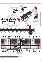
[E2] Aufzugring
[E2] Elevator ring
[E2] Aufzugring
[E2] Elevator ring
[E3] Aufzugdeckel
[E3] Elevator cover
[G1] Antrieb
[G1] Gearbox
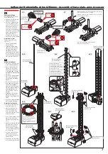
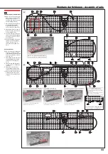
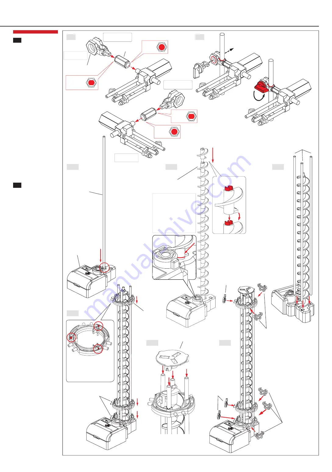
Aufbau des Aufzuges
1. Stecken Sie eine 391mm-Ach-
se in den Antrieb (Abb. 08-1)
2. Die 16-teilige Aufzugspirale
auf die Achse setzen (Abb.
08-2). Achse in den Boden
stecken (Abb. 08-1). Richtige
Drehrichtung der Aufzugspirale
beachten
3. Stecken Sie 3 weitere 391mm-
Achsen in die dafür vorgese-
henen Positionen im Antrieb
(Abb. 08-3)
4. Lassen Sie die 3 Achsen ein-
rasten (Abb. 08-4). Beachten
Sie beim Zusammnbau die
genaue Position der 3 Aufzug-
ringe. Die exakten Positionen
der Aufzugringe finden Sie
auf den Seiten 8 + 9 dieser
Anleitung
5. Verbinden Sie die 4 Achsen
nun mit dem Aufzugdeckel
(Abb. 08-5). Auf richtigen Sitz
achten
6. Nun die 3 Schienenhalterungen
[A6] befestigen (Abb. 08-6)
Assembly of the elevator
1. Insert the 391mm shaft into
the gearbox (fig. 08-1)
2. Slide the elevator (16 pcs)
onto the shaft (fig. 08-2).
Insert shaft into base (fig.
08-1). Please note the correct
direction of rotation
3. Insert 3 further 391mm shafts
into the exact pre-defined
positions on the gearbox (fig.
08-3)
4. Allow the 3 shafts to snap into
place (pic. 08-4). Take care
that the elevator rings are
properly located. See page 8
+ 9 for the proper locations of
the elevator rings
5. Insert the 4 shafts into the
elevator cover (fig. 08-5).
Take care that the shafts are
properly located
6. Now attach 3 rail stands [A6]
to the elevator ring (fig. 08-6)
7
3
4
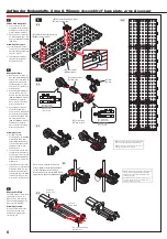
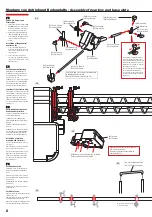
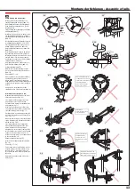
Montage der Wippe
Befestigung der Wippe an der
Achse (Abb. 06 + 07)
1. Verbinden Sie die Wippe mit
Armhalter B (Abb. 06)
2. Stecken Sie Armhalter B auf
die Achse (Abb. 07). Siehe
auch Seite E1-E4 für weitere
Informationen zu Montage
der Arme. Stecken Sie die
Arretierung in den Armhalter B
und drehen Sie die Arretierung
um 90° (Abb. 03). Hinweis:
Um den Armwinkel zu
verändern, muss vorher die
Fixierung wieder gelöst werden
Assembly of seesaw
Attach seesaw to the shaft
(fig. 06 + 07)
1. Connect seesaw with arm
holder B (fig. 06)
2. Attach arm holder B to the
shaft (fig. 07). Refer to the
assembly of arms (page 10
and following). Insert arm
wrench into arm holder B and
turn it by 90 degrees (fig. 03).
Note: To modify the angle of the
arm, release the fixation first
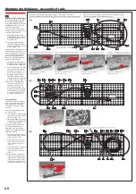
Aufbau der Bodenplatte, Arme & Wippen -
Assembly of base plate, arms & seesaw
06
07
08-1
08-4
08-5
08-6
08-2
08-3
[A3] Aufsteckhülse
[A3] Arm tube
[A4] Armhalter B
[A4] Arm holder B
rechtsseitig anbauen
mount right hand side
linksseitig anbauen
mount left hand side
1 Stück aufbauen
Install 1 pcs
1 Stück aufbauen
Install 1 pcs
Lochprofil
Hole profile
Lochprofil
Hole profile
Lochprofil
Hole profile
Lochprofil
Hole profile
Wippe nach dem Zusammenbau feinjustieren
Adjust seesaw after assemby
Hinweis:
Beim Drehen der Arretierung darauf achten, dass der
Arm in der gewünschten Position bleibt
Note:
When turning the arm wrench, make sure not to change
the right position of the arm
[S1] Achse 391mm
[S1] Shaft 391mm
[S1] Achse 391mm
[S1] Shaft 391mm
[E1] Aufzugspirale
[E1] Elevator helix
Zwischen Antrieb und
Aufzugspirale darf kein Spalt
entstehen, da der Aufzug sonst
nicht richtig funktioniert. Richtige
Drehrichtung beachten
Avoid that there is a gap between
gearbox and elevator helix.
Otherwise the elevator will not
operate properly. Please note the
correct direction of rotation
Konvex gewölbtes, rotes Teil
zeigt nach oben. Unbedingt auf
richtigen Sitz achten
Make sure convex red parts point
up and everything is correctly
seated.


