background image

10

   |   Optidrive ODE-3 User Guide   |   

Version 1.00

www.invertekdrives.com

3

Mech

anical Installation

3.4. Guidelines for Enclosure Mounting

  

IP20 drives are suitable for use in pollution degree 1 environments, according to IEC-664-1. For pollution degree 2 or higher 
environments, drives should be mounted in a suitable control cabinet with sufficient ingress protection to maintain a pollution 
degree 1 environment around the drive.

  

Enclosures should be made from a thermally conductive material.

  

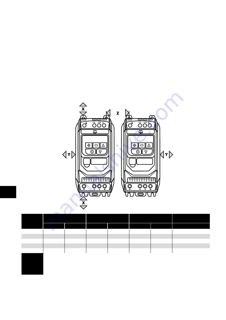
Ensure the minimum air gap clearances around the drive as shown below are observed when mounting the drive.

  

Where ventilated enclosures are used, there should be venting above the drive and below the drive to ensure good air circulation. 
Air should be drawn in below the drive and expelled above the drive.

  

In any environments where the conditions require it, the enclosure must be designed to protect the Optidrive against ingress of 
airborne dust, corrosive gases or liquids, conductive contaminants (such as condensation, carbon dust, and metallic particles) and 
sprays or splashing water from all directions.

  

High moisture, salt or chemical content environments should use a suitably sealed (non-vented) enclosure. 

  

The enclosure design and layout should ensure that the adequate ventilation paths and clearances are left to allow air to circulate 
through the drive heatsink. Invertek Drives recommend the following minimum sizes for drives mounted in non-ventilated metallic 
enclosures:

Drive Size

Above & Below

Either Side

Between

Recommended  

airflow

mm

in

mm

in

mm

in

CFM (ft3/min)

1

50

1.97

50

1.97

33

1.30

11

2

75

2.95

50

1.97

46

1.81

22

3

100

3.94

50

1.97

52

2.05

60

4

100

3.94

50

1.97

52

2.05

120

5

200

7.87

25

0.98

70

2.76

104

NOTE

Dimension Z assumes that the drives are mounted side-by-side with no clearance.
Typical drive heat losses are 3% of operating load conditions.
Above are guidelines only and the operating ambient temperature of the drive MUST be 

maintained at all times.

Summary of Contents for ODE-3-110023-1012

Page 1: ...ingle and 3 Phase Input 1 2 3 4 5 6 7 8 9 10 User Manual Quick Start Up General Information and Ratings Mechanical Installation Power Control Wiring Operation Parameters Analog and Digital Input Macro Configurations Modbus RTU Communications Technical Data Troubleshooting EMC L1 L2 L3 ...

Page 2: ... 1 Managing the Keypad 16 5 2 Operating Displays 16 5 3 Changing Parameters 16 5 4 Read Only Parameter Access 17 5 5 Resetting Parameters 17 5 6 Resetting a Fault 17 6 Parameters 18 6 1 Standard Parameters 18 6 2 Extended Parameters 20 6 3 Advanced Parameters 25 6 4 P 00 Read Only Status Parameters 26 7 Analog and Digital Input Macro Configurations 27 7 1 Overview 27 7 2 Example Connection Diagram...

Page 3: ...adjustment of the operating parameters of the drive incorrect matching of the drive to the motor incorrect installation unacceptable dust moisture corrosive substances excessive vibration or ambient temperatures outside of the design specification The local distributor may offer different terms and conditions at their discretion and in all cases concerning warranty the local distributor should be ...

Page 4: ...ng to any local legislation or codes Do not carry out any work on the drive control cables whilst power is applied to the drive or to the external control circuits Danger Indicates a potentially hazardous situation other than electrical which if not avoided could result in damage to property Within the European Union all machinery in which this product is used must comply with Directive 2006 42 EC...

Page 5: ...e supply type is IT or corner grounded disconnect the EMC filter before connecting the supply 9 5 EMC Filter Disconnect 36 7 Check the supply cable and motor cable for faults or short circuits 8 Route the cables 9 Check that the intended motor is suitable for use noting any precautions recommended by the supplier or manufacturer 4 9 EMC Compliant Installation 15 10 Check the motor terminal box for...

Page 6: ...e time periods for which they must be applied are shown in the following table Following completion of the procedure the drive may be operated as normal 100 75 50 25 T1 T2 T3 T4 Storage Period Power OFF Period Initial Input Voltage Level Time Period T1 Secondary Input Voltage Level Time Period T2 Third Input Voltage Level Time Period T3 Final Input Voltage Level Time Period T4 Up to 1 Year 100 N A...

Page 7: ... Without Filter N A ODE 3 1 10023 1012 0 5 2 3 1 N A ODE 3 1 10043 1012 1 4 3 1 N A ODE 3 210058 1042 1 5 5 8 2 200 240V 10 1 Phase Input 3 Phase Output Model Number kW HP Output Current A Frame Size With Filter Without Filter ODE 3 120023 1F12 ODE 3 120023 1012 0 37 0 5 2 3 1 ODE 3 120043 1F12 ODE 3 120043 1012 0 75 1 4 3 1 ODE 3 120070 1F12 ODE 3 120070 1012 1 5 2 7 1 ODE 3 220070 1F42 ODE 3 220...

Page 8: ...F12 ODE 3 140041 3012 1 5 2 4 1 1 ODE 3 240041 3F42 ODE 3 240041 3042 1 5 2 4 1 2 ODE 3 240058 3F42 ODE 3 240058 3042 2 2 3 5 8 2 ODE 3 240095 3F42 ODE 3 240095 3042 4 5 9 5 2 ODE 3 340140 3F42 ODE 3 340140 3042 5 5 7 5 14 3 ODE 3 340180 3F42 ODE 3 340180 3042 7 5 10 18 3 ODE 3 340240 3F42 ODE 3 340240 3042 1 1 15 24 3 ODE 3 440300 3F42 ODE 3 440300 3042 15 20 30 4 ODE 3 440390 3F42 ODE 3 440390 3...

Page 9: ...he cooling requirements of the Optidrive 3 2 UL Compliant Installation Refer to section 9 4 Additional Information for UL Compliance on page 35 for Additional Information for UL Compliance 3 3 Mechanical Dimensions and Mounting IP20 Open Units L1 L L3 L2 N Drive Size A B C D E F Weight mm in mm in mm in mm in mm in mm in Kg Ib 1 173 6 81 83 3 27 123 4 84 162 6 38 50 1 97 50 1 97 1 0 2 2 2 221 8 70...

Page 10: ... the Optidrive against ingress of airborne dust corrosive gases or liquids conductive contaminants such as condensation carbon dust and metallic particles and sprays or splashing water from all directions High moisture salt or chemical content environments should use a suitably sealed non vented enclosure The enclosure design and layout should ensure that the adequate ventilation paths and clearan...

Page 11: ...o the requirements of national and local industrial safety regulations and or electrical codes The integrity of all ground connections should be checked periodically Protective Earth Conductor The Cross sectional area of the PE Conductor must be at least equal to that of the incoming supply conductor Safety Ground This is the safety ground for the drive that is required by code One of these points...

Page 12: ...uit current at the Optidrive Power terminals as defined in IEC60439 1 is 100kA 4 3 3 Optional Input Choke An optional Input Choke is recommended to be installed in the supply line for drives where any of the following conditions occur o The incoming supply impedance is low or the fault level short circuit current is high o The supply is prone to dips or brown outs o An imbalance exists on the supp...

Page 13: ...AC should not be routed in the same cable Maximum control terminal tightening torque is 0 5Nm Control Cable entry conductor size 0 05 2 5mm2 30 12 AWG 4 7 Control Terminal Connections Default Connections Control Terminal Signal Description 1 24Vdc User Output 24Vdc user output 100mA Do not connect an external voltage source to this terminal 2 Digital Input 1 Positive logic Logic 1 input voltage ra...

Page 14: ... or PID feedback for example is defined by parameters P 15 The function of these parameters and available options is described in section 7 Analog and Digital Input Macro Configurations on page 27 4 7 4 Digital Inputs Up to four digital inputs are available The function of the inputs is defined by parameters P 12 and P 15 which are explained in section 7 Analog and Digital Input Macro Configuratio...

Page 15: ...C1 radiated emissions additional measures may be required contact your Sales Partner for further assistance 7 Permissible cable length with additional external EMC filter 4 10 Optional Brake Resistor Optidrive E3 Frame Size 2 and above units have a built in Brake Transistor This allows an external resistor to be connected to the drive to provide improved braking torque in applications that require...

Page 16: ...hen in keypad mode used to Start a stopped drive or to reverse the direction of rotation if bi directional keypad mode is enabled 5 2 Operating Displays Drive Stopped Disabled Drive is enabled running display shows the output frequency Hz Press the Navigate key for 1 second The display will show the motor current Amps Press the Navigate key for 1 second The display will show the motor power kW If ...

Page 17: ...ect the required Read Only parameter Press the Navigate key for 1 second to display the value Press and hold the Navigate key 2 seconds to return to the operating display 5 5 Resetting Parameters Press the Stop key The display will show To reset parameter values to their factory default settings press and hold Up Down and Stop buttons for 2 seconds The display will show 5 6 Resetting a Fault Press...

Page 18: ...ge sudden step changes in load or for PI control applications Optidrive Energy Optimisation reduces the drive internal heat losses increasing efficiency however it may result in some vibration in the motor during light load operation In general this function is suited to Fan Pump and Compressor applications Setting Motor Energy Optimisation Optidrive Energy Optimisation 0 Disabled Disabled 1 Enabl...

Page 19: ...everse directions u using the internal keypad or an external remote Keypad Pressing the keypad START button toggles between forward and reverse 3 Modbus Network Control Control via Modbus RTU RS485 using the internal Accel Decel ramps 4 Modbus Network Control Control via Modbus RTU RS485 interface with Accel Decel ramps updated via Modbus 5 PI Control User PI control with external feedback signal ...

Page 20: ...ill be connected 0 Drive Enabled Running Logic 1 when the motor is enabled 1 Drive Healthy Logic 1 when power is applied to the drive and no fault exists 2 At Target Frequency Speed Logic 1 when the output frequency matches the setpoint frequency 3 Drive Tripped Logic 1 when the drive is in a fault condition 4 Output Frequency Limit Logic 1 when the output frequency exceeds the adjustable limit se...

Page 21: ...imit of the band P 28 V F Characteristic Adjustment Voltage 0 P 07 0 V P 29 V F Characteristic Adjustment Voltage 0 0 P 09 0 0 Hz This parameter in conjunction with P 28 sets a frequency point at which the voltage set in P 29 is applied to the motor Care must be taken to avoid overheating and damaging the motor when using this feature P 30 Start Mode Automatic Restart Fire Mode Operation Index 1 S...

Page 22: ...ctive during this phase This can be used to ensure the motor is at standstill prior to starting 2 DC Injection on Start Stop DC injection applied as both settings 0 and 1 above P 33 Spin Start 0 2 0 0 Disabled 1 Enabled When enabled on start up the drive will attempt to determine if the motor is already rotating and will begin to control the motor from its current speed A short delay may be observ...

Page 23: ...g Factor 0 000 16 000 0 000 Index 2 Display Scaling Source 0 3 0 Allows the user to program the Optidrive to display an alternative output unit scaled from either output frequency Hz Motor Speed RPM or the signal level of PI feedback when operating in PI Mode Index 1 Used to set the scaling multiplier The chosen source value is multiplied by this factor Index 2 Defines the scaling source as follow...

Page 24: ...ve will trip and show the fault code if the signal level falls below 3mA 20 to 4mA Signal the Optidrive will run at Preset Speed 1 P 20 if the signal level falls below 3mA Use for motor thermistor measurement valid with any setting of P 15 that has Input 3 as E Trip Trip level 1 5kΩ reset 1kΩ P 48 Standby Mode Timer 0 0 60 0 0 0 s When standby mode is enabled by setting P 48 0 0 the drive will ent...

Page 25: ...istance in Ohms Determined by Autotune adjustment is not normally required P 56 Motor Stator d axis Inductance Lsd 0 00 655 35 mH Determined by Autotune adjustment is not normally required P 57 Motor Stator q axis Inductance Lsq 0 00 655 35 mH Determined by Autotune adjustment is not normally required P 58 DC Injection Speed 0 0 P 01 0 0 Hz RPM Sets the speed at which DC injection current is appli...

Page 26: ...tgoing process data TX PDO1 for CAN PO1 PO2 PO3 PO4 P00 23 Accumulated time with heatsink 85 C Hours Total accumulated hours and minutes of operation above heatsink temp of 85 C P00 24 Accumulated time with drive internal temp 80 C Hours Total accumulated hours and minutes of operation with drive internal ambient above 80 C P00 25 Estimated rotor speed Hz In vector control modes estimated rotor sp...

Page 27: ...analog input 2 e g 0 10 Volt 4 20mA 7 2 Example Connection Diagrams The diagrams below provide an overview of the functions of each terminal macro function and a simplified connection diagram for each Diagram 1 Diagram 2 Diagram 3 Diagram 4 24V DC DI 1 DI 2 DI 3 10V DC AI 1 0V COM 24V DC DI 1 DI 2 DI 3 10V DC AI 1 0V COM 24V DC DI 1 DI 2 DI 3 10V DC AI 1 0V COM 24V DC DI 1 DI 2 DI 3 10V DC AI 1 0V...

Page 28: ...tarily to START the drive in the reverse direction NC STOP Input must be maintained FAST STOP P 24 When both inputs are momentarily active simultaneously the drive stops using Fast Stop Ramp Time P 24 FAST STOP P 24 Normally Closed Falling Edge Open momentarily to FAST STOP the drive using Fast Stop Ramp Time P 24 E TRIP Normally Closed External Trip input When the input opens momentarily the driv...

Page 29: ...Analog Input AI1 3 FAST STOP P 24 8 STOP RUN FWD REV DI3 DI4 PR 2 0 0 P 20 1 0 P 21 0 1 P 22 1 1 P 23 9 STOP START FWD STOP START REV DI3 DI4 PR 2 FAST STOP P 24 0 0 P 20 1 0 P 21 0 1 P 22 1 1 P 23 10 NO START STOP NC AI1 REF P 20 REF Analog Input AI1 5 11 NO START FWD STOP NC NO START REV Analog Input AI1 6 FAST STOP P 24 12 STOP RUN FAST STOP P 24 OK AI1 REF P 20 REF Analog Input AI1 7 13 NO STA...

Page 30: ...ased once for each rising edge The step of each speed change is defined by the absolute value of Pre set Speed 1 P 20 Speed change only happens during normal running condition no stop command etc Digital pot will be adjusted between minimum speed P 02 and maximum speed P 01 7 6 Macro Functions Fieldbus Control Mode P 12 3 4 7 8 or 9 P 15 DI1 DI2 DI3 AI2 DI4 AI1 Diagram 0 1 0 1 0 1 0 1 0 STOP ENABL...

Page 31: ... in emergency conditions until the drive is no longer capable of sustaining operation The Fire Mode input may be a normally open Close to Activate Fire Mode or Normally Closed Open to Activate Fire Mode according to the setting of P 30 Index 2 In addition the input may be momentary or maintained type selected by P 30 Index 3 This input may be linked to a fire control system to allow maintained ope...

Page 32: ...n section 7 6 Macro Functions Fieldbus Control Mode P 12 3 4 7 8 or 9 1 CAN 2 CAN 3 0 Volts 4 RS485 PC 5 RS485 PC 6 24 Volt 7 RS485 Modbus RTU 8 RS485 Modbus RTU Warning This is not an Ethernet connection Do not connect directly to an Ethernet port Modbus RTU RS485 Controller RS485 RS485 0 Volt Common Ground NOTES Use 3 or 4 Conductor Twisted Pair Cable RS485 and RS485 must be twisted pair Ensure ...

Page 33: ...ncy in Hz x10 e g 100 10 0Hz 8 R Output Motor Current 0 480 Output Motor Current in Amps x10 e g 10 1 0 Amps 1 1 R Digital input status 0 15 Indicates the status of the 4 digital inputs Lowest Bit 1 Input 1 20 P00 01 R Analog Input 1 value 0 1000 Analog input of full scale x10 e g 1000 100 21 P00 02 R Analog Input 2 value 0 1000 Analog input of full scale x10 e g 1000 100 22 P00 03 R Speed Referen...

Page 34: ...8 7 100 2 2 2 3 19 2 25 25 8 8 10 5 50 3 4 5 29 2 40 40 8 8 15 3 25 200 240 10 V 3 Phase Input 3 Phase Output 1 0 37 0 5 3 4 6 6 8 8 2 3 1 0 75 1 5 6 10 10 8 8 4 3 1 1 5 2 9 5 16 15 8 8 7 2 1 5 2 8 9 16 15 8 8 7 100 2 2 2 3 12 1 16 17 5 8 8 10 5 50 3 4 5 20 9 32 30 8 8 18 25 3 5 5 7 5 26 4 40 35 8 8 24 20 4 7 5 10 33 3 40 45 16 5 30 15 4 1 1 15 50 1 63 70 16 5 46 10 5 15 20 54 6 80 70 25 2 61 10 5...

Page 35: ...rotected by fuses as shown above Mechanical Installation Requirements All Optidrive E3 units are intended for indoor installation within controlled environments which meet the condition limits shown in section 9 1 Environmental The drive can be operated within an ambient temperature range as stated in section 9 1 Environmental For IP20 units installation is required in a pollution degree 1 environ...

Page 36: ...ne voltage transients typically originating from lightning strikes or switching of high power equipment on the same supply When carrying out a HiPot Flash test on an installation in which the drive is built the voltage surge suppression components may cause the test to fail To accommodate this type of system HiPot test the voltage surge suppression components can be disconnected by removing the VA...

Page 37: ... connected check if the motor is too hot 12 Optibus comms loss Check communication link between drive and external devices Make sure each drive in the network has its unique address 13 DC bus ripple too high Check incoming supply phases are all present and balanced 14 Input phase loss trip Check incoming power supply phases are present and balanced 15 Output Over Current Check for short circuits o...

Page 38: ...38 Optidrive ODE 3 User Guide Version 1 00 www invertekdrives com ...

Page 39: ...Version 1 00 Optidrive ODE 3 User Guide 39 www invertekdrives com ...

Page 40: ...Ñ82 E3I20 IN_V1 00wÓ 82 E3I20 IN_V1 00 Invertek Drives Ltd Offa s Dyke Business Park Welshpool Powys SY21 8JF United Kingdom Tel 44 0 1938 556868 Fax 44 0 1938 556869 www invertekdrives com ...

Reviews: