background image

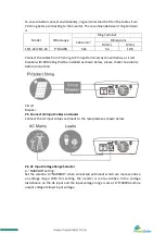
Program 

Description 

Selectable option & behavior 

LCD setting display 

AC input voltage 

range 

Wide(default): if selected, acceptable 

AC input voltage range will be within 

90-280VAC

Narrow: If selected, acceptable AC 

input voltage range will be within 

170-280VAC 

Output source 

priority: to 

configure 

load power 

source 

priority 

Solar first(default): solar energy 

provide power 

to the loads as first priority. 

If solar energy is not enough to power 

all 

connected loads, battery energy will 

supply 

power the load at the same time. 

Utility provides power to the loads 

only when 

any below condition happens: 

-Solar energy is not available

-Battery voltage drop to either 

low-level waning 

voltage or the setting point is 

program 5. 

Utility first: Utility will provide power 

to the loads as priority. Solar and 

battery energy will provide power to 

the load only when utility power Is 

not available.   

SbU: Solar energy provides power to 

the loads as priority.   

If solar energy is not enough to power 

all   

connected loads, battery energy will 

supply   

power the load at the same time.   

Utility provides power to the loads 

only when battery voltage drops to 

either low-level waning voltage or the 

setting point Is program 5. 

Charger source 

priority   

To configure charger 

source priority 

Solar first: solar energy will charge 

battery as priority. 

Utility will charge battery only when 

solar energy is not available 

Utility first: utility will charge battery 

as first   

Solar energy will charge battery only 

when utility power is not available   

Solar and Utility (default): Solar 

energy and utility will charge battery 

at the same time. 

Summary of Contents for SICM16H24

Page 1: ...INSTRUCTION MANUAL SICM8H12 SICM16H24 PLEASE READ THIS MANUAL CAREFULLY BEFORE USING THE MACHINE www investsolar co za ...

Page 2: ...to direct sunlight rainfall or snow Before performing any maintenance on the product please disconnect all power sources AC mains batteries solar panel to avoid the risk of electrical shock Do not attempt to disassemble or repair the product Only authorized personnel are allowed to perform repair While performing maintenance or cleaning especially on the batteries where hazardous liquid might be t...

Page 3: ...e its stated specifications operating parameters and application Acts of third parties atmospheric discharges excess voltage chemical influences natural wear and tear and for loss and damage in transit Improper testing operation maintenance adjustment repair or any modification of any kind not authorized in writing by the supplier The product has been connected to other equipment with which it is ...

Page 4: ...9 2 3 Batteries 9 2 4 PV solar string 11 2 5 Connect AC Input Cables and Loads 12 2 6 AC Input Voltage Range Selector 12 OPERATION 14 3 1 Standby Charging Mode 14 3 2 Operation Modes after powered on 15 3 3 Priority Setting Switch 16 3 4 Fault Mode 17 3 5 LCD Setting 17 SPECIFICATION 21 TROUBLESHOOTING 22 Alarm Behavior Table 23 APPENDIXA 24 APPENDIX B 29 ...

Page 5: ...the power from AC mains if enough sunlight is present The battery can be charged by both AC mains and PV solar string with intelligent charging controller Key features Automatic line to battery switch over Built in enhanced AC charger Built in solar charger controller Configurable output source priority charger source priority charger current and soon High efficient DC to AC conversion with minimi...

Page 6: ...1 1 Product Outlook Front Panel Power ON OFF button Setting function button LCD LED indicators Rear Panel AC input socket AC output socket PV Input terminals Battery terminals DC Fan ...

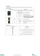
Page 7: ...con indicates level of remaining battery capacity The icon indicates battery flow way If unit is on CC CV charging stages FAST will be lighted The icon indicates output load level If unit work on bypass mode BYPASS will be lighted Indicate PV input voltage PV input current AC input voltage Battery voltage Indicate output voltage output frequency load percentage load VA voltage watt value The icon ...

Page 8: ... seconds Line Mode 2 charge current 3A Green solid lighting Off charge mode Green flashing as cycle 0 5s On 0 5s Off 0 5s On 4s off Yellow Battery mode Yellow solid lighting Red Overload Red flashing every 0 5 second Fault Red lighting Function Keys Function Keys Description To power on off To enter the setting mode or exit setting mode To go to the next selection page To confirm the selection in ...

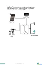
Page 9: ...al Application A typical application diagram for home and office applications is as shown below The inverter can accept AC input from AC mains and is capable of supply various loads such as fluorescent lamp fan ...

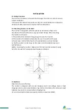
Page 10: ... carry the inverter 2 The location of installation shall allow the user to read the LCD easily 3 Two screws shall be firstly fixed on the wall distance as shown below so that the inverter can be hung on the screws recommended screw size is M4 50 65mm 4 After mounting the inverter make sure it s firmly mounted and won t easily fall off in the event of unexpected earthquake or vibration 2 3 Batterie...

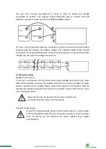
Page 11: ...d to cover the battery terminals during the connection Check the polarity of cables before connecting to the inverter Connect the battery cables to the inverter s battery terminals as shown below Connect with single battery Make sure the battery voltage meets the inverter s specification 12V for 1000VA 1200VA modeland24V for 2000VA 2200VAmodel battery Connect with multiple batteries While connecti...

Page 12: ...ing Selection of PV panel PV string is a connection of PV panels whose output voltage and current vary under different illumination And just like battery the PV panel can be connected in either series or parallel as per needed Please consult the supplier of PV panel so that the operational voltage and current fall within the allowed range of the inverter as set out in the specification Please do n...

Page 13: ...aker with 80A rating shall be installed as shown below please check the polarity before connection Circuit Breaker 2 5 Connect AC Input Cables and Loads Connect the AC input cables and loads to the receptacles as shown below 2 6 AC Input Voltage Range Selector A NARROW setting Set the selector to NARROW when connected with loads which are more sensitive on voltage range With this setting the inver...

Page 14: ...inverter s input voltage range is extended to 90 280VAC while output voltage follows input voltage Please note that the inverter s transfer time switching from Line Mode to Backup Mode gets longer as the input voltage gets low Under the circumstance connecting the inverter with loads which are sensitive to transfer time e g computer might result in power interruption ...

Page 15: ...s called Standby Charging Mode When AC input cable and battery is connected the inverter will enter Standby Charging Mode and LCD will be turned on with the following display If PV string is also connected with enough voltage the display will be as shown below to indicate the power flow from PV string Even if AC input is absent PV power can still charge the battery and the display will be as shown...

Page 16: ...y enter either of the operation mode according to the condition of LINE MODE1 AC input power is present but there is no PV power e g nighttime Load is supplied by AC input power directly LINE MODE 2 Both AC input and PV input are present Load is supplied by either AC input or PV input depending on the priority switch s setting ...

Page 17: ...med an energy saving operation BACKUP MODE 1 Both AC input and PV input are absent The backup power to load comes only from battery The backup time is determined by the capacity of battery BACKUP MODE 2 AC input is absent and PV power is not enough to support loads completely The insufficient power is covered by battery The larger the PV power the less consumption from battery and therefore the lo...

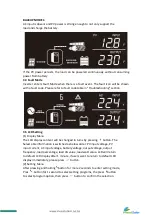
Page 18: ...e LCD display content will be changed in turns by pressing button The Select able information is switched as below order PV input voltage PV input current AC input voltage battery voltage output voltage output frequency load percentage load VA value load watt value LCD will return to default LCD display after 1 minute if users want to return to default LCD display immediately please press button 2...

Page 19: ...oint is program 5 Utility first Utility will provide power to the loads as priority Solar and battery energy will provide power to the load only when utility power Is not available SbU Solar energy provides power to the loads as priority If solar energy is not enough to power all connected loads battery energy will supply power the load at the same time Utility provides power to the loads only whe...

Page 20: ...A model 21V 21 5V 22V default 22 5V 23V 23 5V 24V 24 5V 6 Max charging current To configure total charging current for solar and utility chargers Max charging current utility charging current solar charging current Options in 1 K 1 2KVA model 20A 30A 40A 50A 60A default 70A 80A Options in 2K 2 2KVA model 20A 30A 40A 50A 60A default 75A 7 Max utility charging current Options in 1 K 1 2KVA model 0A ...

Page 21: ...w DC cut off voltage will be related to load percent 10 0V for 12V model 60 load 10 5V for 12V model 60 load 20 0V for 24V model 60 load 21 0V for 24V model 60 load Setting range is from 10 0V to 12 0V for 12V model 20 0Vto 24 0V for 24V model Increment of each click is 0 2V per step 10 LED Light control LED light off LED light on default 11 Recover manufactory setting Recover enable Recover disab...

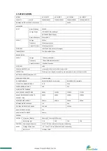
Page 22: ...ECTION Discharge over charged over loading over temperature short circuit protection BATTERY CHARGER powered by AC CHARGING ALGORITHM 3 step charging AC CHARGING MOD 0A 5A 10A 15A 2OA selectable 0A 5A 10A 15A selectable FLOATING CHARGING VOLTAGE 13 7V 27 4V OVERCHARGING VOLTAGE 16V 32V SOLAR BATTERY CHARGER MAX PV PANEL ARRAY POWER 900W 1050W 1500W 1750W MAX PV MODE POWER RATING TO SUPPORT LOAD 50...

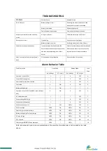
Page 23: ...ance Solar is normal but Solar charger doesn t work P V reverse polarity protection Re connect the P V terminals Alarm Behavior Table Fault Description Line Mode Backup Mode Fault Code No of Beeps AC Output No of Beeps AC Output Overload 1 Vou 195V 0 OFF 0 Output RMS voltage low 2 OFF 2 Over temperature Short circuited 3 OFF 3 Fan locked 4 ON 4 OFF 4 Battery voltage high 5 ON 5 Overload 2 Vou2195V...

Page 24: ...ge and current of the string is When connecting the above PV string in parallel the max voltage and current of the total string is In either case the total output power is Ptotal Ppanel X Number of PV panel The guideline to select and configure PV string is Itotal shall be equal or slightly larger than the max capacity of solar battery charger 50A for 1000VA 2000VA model and 60A for 1200VA 2200VA ...

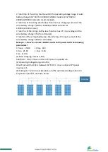
Page 25: ...e of the solar battery charger 55V for all model Total Isc of the string shall be less than the max PV input current of the solar battery charger 65A for all model Example 1 How to connect 1000VA model to PV panels with the following parameters Pmax 150W Vmp 18V Voc 21 6V Imp 8 2A lsc 8 75A 1 Max charging current is 50A 50A 8 2A 6 09 max number of PV panel in parallel is 6 2 Operating Voltage Rang...

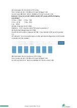
Page 26: ... Isc 8 75A 5 Max charging current is 60A 60A 8 2A 7 31 max Number of PV panel in parallel is 7 6 Operating Voltage Range is 16 18V One PV Panel Vmp 18V is between 16 18V max Number of PV panel in parallel is 1 7 Taking 1 2 into consideration and the optimized configuration is 6 PV panels in parallel as shown below 8 Check again the Voc and the Isc of PV string Voc of string is 21 6V 55V Max PV Inp...

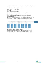
Page 27: ... 2 Operating Voltage Range is 32 36V One PV panel Vmp 30 96V is between 32 36V max Number of PV panel in parallel is 1 3 Taking 1 2 into consideration the optimized configuration is 1 PV panels in series as a string and 6 strings in parallel as shown below 4 Check again the Voc and Isc of PV string Voc of string is 1x36 6V 36 6V 55V Max PV Input Voltage OK Isc of string is 6x8 75A 52 5A 65A Max PV...

Page 28: ... 6 Operating Voltage Range is 32 36V One PV panel Vmp 30 96V is between 32 36V max Number of PV panel in parallel is 1 7 Taking 1 2 into consideration the optimized configuration is 1 PV panels in series as a string and 6 strings in parallel as shown below 8 Check again the Voc and Isc of PV string Voc of string is 1x36 6V 36 6V 55V Max PV Input Voltage OK Isc of string is 7x8 75A 61 25A 65A Max P...

Page 29: ...tput source priority setting 1 Setting Utility as output source Priority Utl 1 1 When utility is normal The loads connected to the product are supplied by utility power only even when solar power presents 1 2 When utility is down As soon as the utility is down the inverter enters Backup Mode and checks both solar power and battery s status If solar power is strong enough it will supply the loads i...

Page 30: ...will not be consumed even though it s available If solar power is not enough battery will firstly come up to support the loads and after battery is low or the setting point in program 5 utility will then take over to support the loads and charge the battery 3 2 When utility is down The behavior is the same as 1 2 Advantages Disadvantages Risk The good utilization of solar power Save electricity bi...

Page 31: ...en utility is normal Solar energy and utility will charge battery at the same time 4 2 When utility is down Solar energy will charge battery Summary Whether setting which option as charger source priority subject to purpose of installing the product In the event the product is to be installed in areas where the utility power is unstable and backup function is much important than energy saving Sola...

Reviews: