22
Both the IPC-S and IPC-T Invicta models, are equipped with two 12volt, 31Ah Gel-
Cell Batteries, connected in series.
Their maximum driving range is 15miles, but this can vary depending on driving
conditions.
As they are not designed to be frequently removed and refitted they would normally
only require removal for fault diagnosis, maintenance or replacement.
WARNINGS:
Other than for testing purposes by suitably trained personnel, always
ensure the power is turned “OFF” before any maintenance is carried out on
the wheelchair, especially where removal of the Batteries is required.
Batteries - Removal and Refitting.
Before commencing this procedure, the wheelchair
should be vacated and parked on a firm level surface,
with both Parking Brakes applied and the Drive Selector
Lever set to the “Drive” position, Fig.9.
Disconnection and removal of the Batteries will require
removal of the Seat Unit from the wheelchair.
Tools Required: 2 x 10mm Spanners
Please follow instructions:-
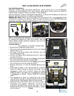
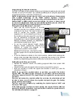
Turn “OFF” power at the Remote Controller Fig.20.
Disconnect the Remote Control Cable from the Power
Base loom at the grey/black connector, Fig.21. The
Power Tilt Actuator Cable on the IPC-T model, must
also be disconnected at the white/black connector
Fig.22. Both located just forward of the rear main
Chassis.
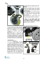
Remove both Sidearms complete with the Remote
Controller Fig.8.
NOTE:
If the Wheelchair is fitted with
an activity/feeding Tray, this must be removed prior to
removing the Sidearms.
Disconnect and remove both Footrest Hangers. Fig.9.
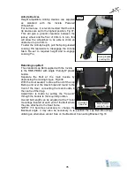
Unscrew the front Seat Retaining Screw, located
behind the front Seat Mount, Fig.3a, sufficiently to
allow the front of the Seat to be lifted.
With one person standing either side of the
wheelchair, the Seat Unit can be lifted upwards and
forwards, clear of the Power Base.
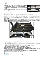
The Batteries are housed in Battery Boxes which are
supported on the wheelchair by two tubular rails
attached to the Frame and retained by Nylon webbing
straps, secured by Velcro and a rear bracket retained by
two hand screws. Figs.23 and 24
Release front and rear Battery Box straps (
a
) and (
b
)
Fig.23 at the Velcro panels. (Not the Battery Box Cover straps Fig.25)
As straps (
c
) and (
d
) Fig.31, are attached to the Battery Box retaining bracket
these will be released when the hand screws and bracket are removed.
[Cont]
BATTERIES REMOVE and REFITTING
ON / OFF
Fig. 20
Remote Control
Cable connector
Power Tilt Cable
Connector
Fig. 21
Fig. 22
Summary of Contents for IPC-S
Page 1: ...Powered Wheelchairs Instructions for Use Models IPC S and IPC T Edition Two Feb 2013...
Page 2: ...2...
Page 41: ...41 USER NOTES...
Page 42: ...USER NOTES...
Page 43: ...USER NOTES...


