Invisible Systems Limited
P a g e
|
9
7-9 Beetham Road, Milnthorpe Cumbria, LA7 7QL, England
Phone: 01539 722 520 Email: info@invisible-systems.com
QC0150 Mains Powered Modbus Transmitter
Installation Manual
6.
Correct connection of the data cables into the Modbus Transmitter
from the Modbus Device.
The data connection is made by three wires from the allocated Modbus Meters into the
Modbus Transmitter, the connection of these cables is important as they are polarity
sensitive and
will not work if connected incorrectly. There is a label located on the side of
the Modbus Transmitter showing correct orientation of the cables for connection.
“
Under no circumstances should the cover be removed while the Transmitter is plugged
in the available mains supply
”
“Under no circumstances should the Transmitter be mounted on any form of asbestos
boards-
Check asbestos register prior to any work commencing”
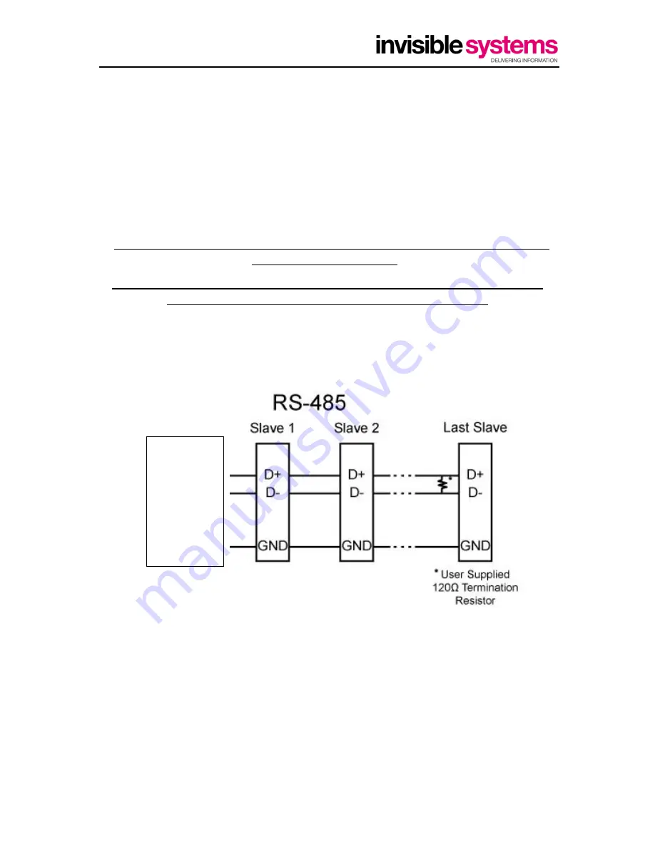
Example-Modbus Connections
As shown each meter is show as a slave, it is advisable that the last meter in the modbus
loop be checked to see if there is a 120 ohm Termination Resistor present. This is more
important where the modbus chain is approaching 100mtrs as the resistor helps
“
clean
”
the
signal being sent by the meters to the Modbus Transmitter.
The installation of the data cable between the Modbus Transmitter and the Modbus Device
must be fitted in such a way that sufficient mechanical protection is provided as per IEE
Wiring Regulations 17
th
Edition
Modbus
Transmitter


