background image


1


PROFESSIONAL WEATHER STATION 

INSTRUCTION MANUAL                     


Model no.: VSPWS1070 


Page   

 
1.  Introduction……………………………………………………………….2 
2.  Inventory of contents…………………………………………..……….2 

Feature of the base station

………………………….……………… .…2 

Feature of wind sensor

………………………………………… ….……2 

Feature of rain sensor

………………………………………… ….….…2 

3.  Set up guide………………………………………………………………3 

3.1 Battery install

………………………………………………… ……...3                                 

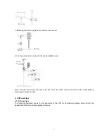
3.2 Mounting

…………………………………………………… ………...4


4.  LCD overview……………………………………………………………..5 

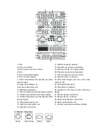
4.1 LCD overview

…………………………………………………………5 

4.2 Weather forecasting

……………………………………………….…6 

      4.3 Weather forecast tendency indicator

……………..………………...7 

      4.4 Storm warning indicator

………………………………

…………….....7


5.  Program modes……………………………………..………………….…7 

5.1 Quick display mode

………………………………………….…….....7 

5.2 Setting mode

…………………………………………….…..………...8 

5.3 History mode

……………………………………….………..…….…..8 

5.4 Alarm mode

…………………………………………………..……..…8 

5.5 Min/Max mode

…………………………………………………….…..10 

6.    Problems and interference with operation………………………....10 
7.  Specification……………………………………………………. …….....11 


This  Operation  Manual  is  part  of  this  product and  should  be  kept  in  a  safe  place  for  future 
reference. It contains important notes on setup and operation. 


www.invisua.co.uk


Summary of Contents for VSPWS1070

Page 1: ...1 LCD overview 5 4 2 Weather forecasting 6 4 3 Weather forecast tendency indicator 7 4 4 Storm warning indicator 7 5 Program modes 7 5 1 Quick display mode 7 5 2 Setting mode 8 5 3 History mode 8 5 4...

Page 2: ...ndoor and outdoor relative humidity displays l Barometric pressure reading in inHg or hPa absolute or relative user selectable l Detailed display of rainfall data in 1 hour 24 hours one week one month...

Page 3: ...the two sockets and insert 2 x AA 1 5V Alkaline batteries and close the cover Every time the thermo hygro sensor is powered up for example after a change of batteries the LED indicator will light up...

Page 4: ...overwrite the manually set time and date If your time zone is not at UTC 1 00 then manually set the time zone so that your clock time will be updated correctly after radio controlled time is received...

Page 5: ...s Once the wind sensor and rain sensor are fixed onto the mast connect the cable to the corresponding thermo hygro sensor socket 4 LCD overview 4 1 LCD overview The following illustration shows the fu...

Page 6: ...al outdoor alarm icon 16 Weather forecast icon 17 Weather tendency indicator 18 Pressure unit relative or absolute 19 Pressure with 24 hour history graph 20 Pressure low alarm and high alarm 21 Pressu...

Page 7: ...a fall over pressure threshold within 3 hours the storm forecasting will be activated the clouds with rain icon and tendency arrows will flash for 3 hours indicating the storm warning feature has been...

Page 8: ...speed and gust display units in km h mph m s knots bft 11 Rainfall display units in mm or inch In the setting modes press key or MIN MAX key to select the units or scrolls the value Holding the key or...

Page 9: ...toggle through each alarm mode until it returns to the normal display mode Press HISTORY key or key idle 30 second at any time the alarm mode will return to Normal Mode Canceling the Temperature Alar...

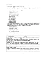
Page 10: ...tdoor humidity minimum 4 Outdoor temperature minimum 5 Wind chill temperature minimum 6 Dew point temperature minimum 7 Pressure minimum Press the HISTORY key or key idle 10 second the Min Max mode wi...

Page 11: ...ne batteries Battery life Minimum 12 months for base station Minimum 24 months for thermo hygro sensor Remark where outdoor temperature is lower than 20 C make sure proper type of batteries to be used...

Reviews: